
heat sink

A technology of heat dissipation device and packaging structure, applied in the direction of instruments, electrical digital data processing, electrical components, etc., can solve the problems of noise generation, thinning cooling fan, and overall height reduction of cooling fan 1', so as to reduce noise and strengthen airflow. flow effect

Active Publication Date: 2017-06-23
AMTEK SEMICON
View PDF3 Cites 0 Cited by
  • Summary
  • Abstract
  • Description
  • Claims
  • Application Information

AI Technical Summary

Problems solved by technology

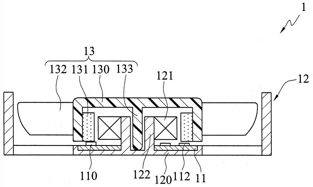
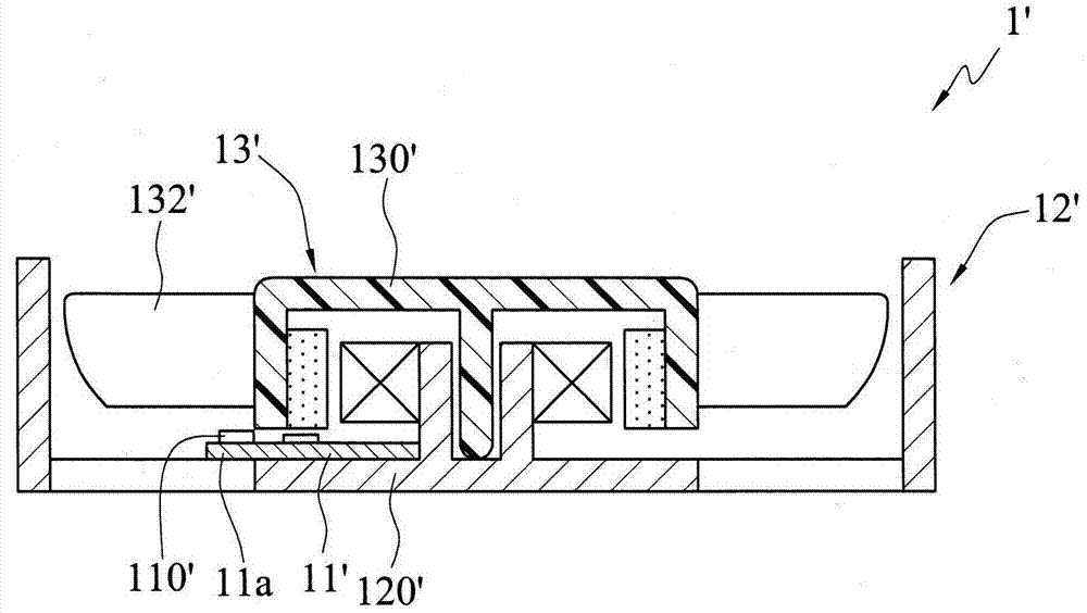
[0008] However, the formation of the outwardly extending portion 11a of the above-mentioned printed circuit board 11' will interfere with the airflow driven by the fan wheel set 13' when it rotates. If the airflow is disturbed, noise will be generated, which will further affect the installation of such a device. The use quality of electronic products with cooling fan 1'
At the same time, because the extension part 11a extends outward, a predetermined distance needs to be maintained between the blade 132' and the control chip 110', which is not conducive to the reduction of the overall height of the existing cooling fan 1', and cannot meet the needs of electronic products. thinning needs
[0009] Moreover, the existing heat dissipation fan 1' disclosed above still needs to arrange the printed circuit board 11' between the hub 130' of the fan wheel set 13' and the base 120' of the housing 12', resulting in the thickness of the printed circuit board 11' It will still affect the overall height of the cooling fan 1', and the cooling fan 1' cannot be further thinned

Method used


Image

  • heat sink
  • heat sink
  • heat sink

Examples


Embodiment Construction

[0069] The implementation of the present invention will be described below through specific specific examples, and those skilled in the art can easily understand other advantages and effects of the present invention from the content disclosed in this specification.

[0070] It should be noted that the structures, proportions, sizes, etc. shown in the drawings attached to this specification are only used to match the content disclosed in the specification for the understanding and reading of those skilled in the art, and are not intended to limit the implementation of the present invention. Limiting conditions, so there is no technical substantive meaning, any modification of structure, change of proportional relationship or adjustment of size, without affecting the effect and purpose of the present invention, should still fall within the scope of the present invention. The disclosed technical content must be within the scope covered. Meanwhile, references in this specification...


PUM


Abstract

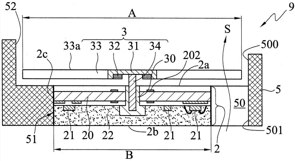
A heat dissipation device, comprising: a semiconductor packaging structure with an inner set subgroup and a semiconductor component, a fan wheel set axially connected to the semiconductor packaging structure, and a flow guide with a guide channel for accommodating the semiconductor package structure and the fan wheel set structure, the fan wheel set has a plurality of blades located above the surface of the semiconductor package structure, and the stator set and the semiconductor component are used to control the movement of the first blade, and the blade is extended to protrude from the semiconductor package structure The side surface is used to increase the size of the blade, so the generated air volume can be increased without changing the size of the semiconductor package structure.

Description

technical field [0001] The invention relates to a heat dissipation device, in particular to a heat dissipation device with a semiconductor packaging structure. Background technique [0002] For example, the circuit board of the main board (Main Board or Mother Board) is equipped with a large number of electronic components (Electronic Components) such as a central processing unit or a graphics card, and the electrical circuits (Conductive Circuits) used to electrically connect the electronic components, These electronic components will generate heat when they function. If the generated heat is not removed from the electronic product equipped with the circuit board, the electronic components will fail due to overheating; this kind of problem is increasing in function requirements and processing speed Faster electronic products are more important, because the increase in function and processing speed means that more or higher-level electronic components or electronic devices m...

Claims


Application Information

Patent Timeline
Patent Type & Authority Patents(China)
IPC IPC(8): H01L23/467G06F1/20
Inventor 黄建屏
Owner AMTEK SEMICON
Learn More