
Energy-saving furnace body structure of large-type pit furnace

A furnace body structure and well-type furnace technology, which is applied in the field of large-scale well-type furnace energy-saving furnace body structure, can solve the problems of affecting the life of large-scale well-type furnaces, poor heating uniformity, and poor heat preservation effect, so that it is not easy to dissipate heat , improve life, reduce the effect of heat radiation

Active Publication Date: 2015-04-15
南通洋口港劳务服务有限公司
View PDF9 Cites 0 Cited by
  • Summary
  • Abstract
  • Description
  • Claims
  • Application Information

AI Technical Summary

Problems solved by technology

[0002] The structure of the existing large-scale well-type furnace is a furnace lining inside the furnace shell, and the heating element is arranged inside the furnace lining. The large-scale well-type furnace with this structure has a poor heat preservation effect, and the power consumption during the heat treatment process of the workpiece is relatively high. Large, long heating time, and due to poor heating uniformity, the quality of the workpiece after heat treatment is not good, and cracks, silver streaks, looseness, etc. will appear
[0003] In addition, the furnace cover of some large-scale well-type furnaces is an integrated structure. When heat-treating large workpieces, the heating elements or linings on the inner wall of the furnace are damaged due to the swing of the workpiece, which not only affects the life of large-scale well-type furnaces, can also cause damage to the workpiece

Method used


Image

  • Energy-saving furnace body structure of large-type pit furnace
  • Energy-saving furnace body structure of large-type pit furnace

Examples


Embodiment Construction

[0017] In order to deepen the understanding of the present invention, the present invention will be further described below in conjunction with the accompanying drawings and embodiments, which are only used to explain the present invention and do not limit the protection scope of the present invention.

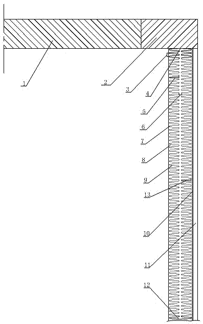
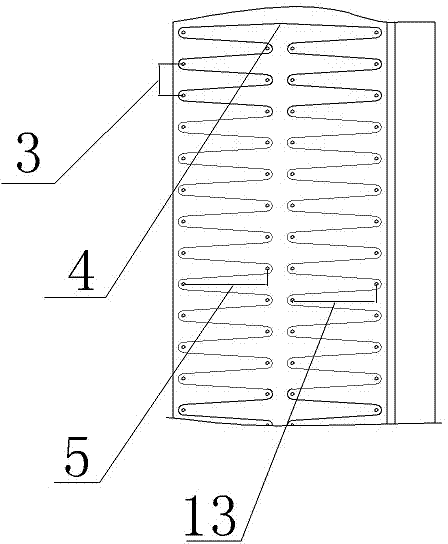
[0018] like figure 1 and figure 2 As shown, a large well-type furnace energy-saving furnace body structure includes a furnace lining 8, a heating element 9, and a furnace shell 11. The furnace shell 11 is set on the outermost layer of the furnace body structure, and the furnace lining 8 is connected to the furnace shell 11. A plurality of heating elements 9 are provided, and four rows of fixing pieces 7 are arranged staggeredly in the furnace lining 8, and each heating element 9 is spirally and evenly wound along the leftmost two rows of fixing pieces 7 and the rightmost two rows of fixing pieces 7 respectively. The two sets of spiral heating elements 9 of each heating elem...


PUM


Abstract

The invention discloses an energy-saving furnace body structure of a large-type pit furnace. The energy-saving furnace body structure comprises a furnace lining, heating elements and a furnace shell. The outmost layer of the furnace body structure is sleeved with the furnace shell, and the furnace lining is connected with the interior of the furnace shell. The energy-saving furnace body structure is characterized in that the heating elements are arranged in the furnace lining, and four rows of fixing parts are arranged in the furnace lining in a staggered manner; the heating elements are evenly and spirally wound along the two rows of fixing parts on the left-most side and the two rows of fixing parts on the right-most side; and the two sets of spiral heating elements are connected at the top end and the bottom end of the furnace lining. According to the structure, heating uniformity of the furnace body structure is improved, and the phenomenon that when workpieces to be heated enter and go out of the furnace body, the workpieces collide with or rub the furnace body, and consequently the furnace body and the workpieces are affected is avoided; heat energy radiation is reduced, and electric energy is saved; and the service life of the furnace body is prolonged, and the quality of the heated workpieces is improved.

Description

technical field [0001] The invention relates to the technical field of large-scale well-type furnace manufacturing, in particular to an energy-saving furnace body structure of a large-scale well-type furnace. Background technique [0002] The structure of the existing large-scale well-type furnace is a furnace lining inside the furnace shell, and the heating element is arranged inside the furnace lining. The large-scale well-type furnace with this structure has a poor heat preservation effect, and the power consumption during the heat treatment process of the workpiece is relatively high. Large, long heating time, and due to poor heating uniformity, the quality of the workpiece after heat treatment is not good, and cracks, silver streaks, looseness, etc. will appear. [0003] In addition, the furnace cover of some large-scale well-type furnaces is an integrated structure. When heat-treating large workpieces, the heating elements or linings on the inner wall of the furnace a...

Claims


Application Information

Patent Timeline
Patent Type & Authority Applications(China)
IPC IPC(8): F27B1/09F27B1/12F27B1/22
Inventor 傅书根沈卫东戴文卫
Owner 南通洋口港劳务服务有限公司
Learn More