Pull-out Chassis Brackets for Cabinets

A bracket device and pull-out technology, which is applied in the direction of support structure installation, etc., can solve the problem that the chassis cannot be pulled out.

Active Publication Date: 2018-01-02
CHINA AVIATION OPTICAL-ELECTRICAL TECH CO LTD
View PDF7 Cites 0 Cited by
  • Summary
  • Abstract
  • Description
  • Claims
  • Application Information

AI Technical Summary

Problems solved by technology

[0004] The purpose of the present invention is to provide a pull-out type chassis bracket device for cabinets, so as to solve the problem that the existing chassis bracket devices for cabinets cannot help and pull out the chassis when removing the chassis

Method used


Image

  • Pull-out Chassis Brackets for Cabinets
  • Pull-out Chassis Brackets for Cabinets
  • Pull-out Chassis Brackets for Cabinets

Examples


Embodiment Construction

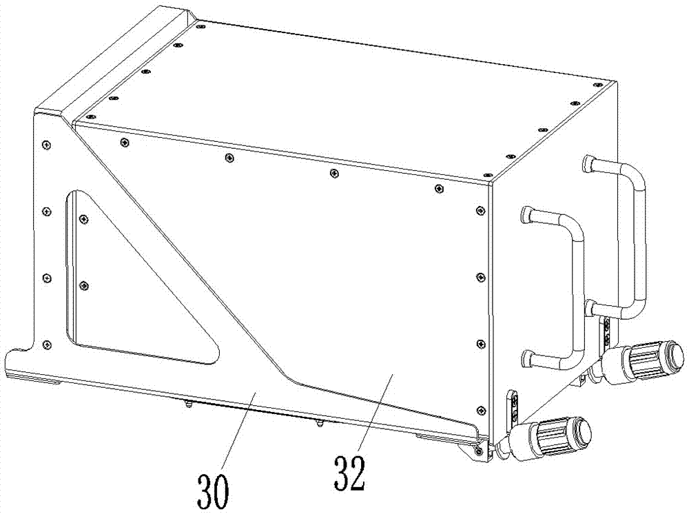
[0023] An embodiment of a chassis bracket device for a cabinet, such as Figure 2-12 As shown, the chassis bracket device includes a bracket 30 and a locking device.

[0024] The structure of the bracket is the prior art, and will not be described in detail here, and the locking device is assembled on the front part of the bracket.

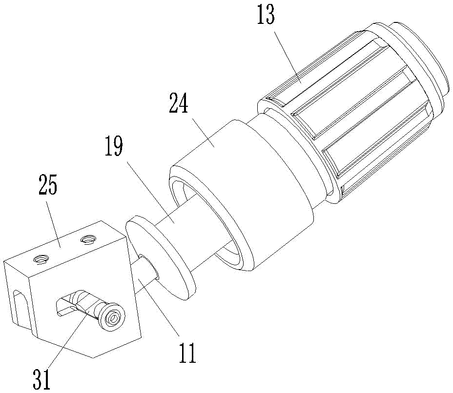
[0025] The locking device includes a locking rod 11, a screw sleeve 12, a screw cap 13, a transmission steel ball 14, a transmission plate 15, a pressure plate 16, a force limiting spring 17, a spring support sleeve 18, an output sleeve 19, a transmission seat 20, a ball 21, Push spring 22, transmission sleeve 23, lock cap 24 and lock seat 25.

[0026] The front end of the locking rod 11 is provided with a hinge hole and a threaded section is provided between the two ends.

[0027] The position between the two ends of the screw sleeve 12 is provided with an internal thread segment, which corresponds to the thread segment on the lock bar 11, and ...


PUM


Abstract

The invention relates to the field of modularized electrical cabinets, in particular to a pull-out type chassis bracket device for a cabinet. The chassis bracket device includes a bracket and a locking device assembled on the front of the bracket. The locking device includes a locking rod and a locking cap. The locking port with the tight hook, the screw sleeve is threaded on the lock rod, and the output sleeve is installed on the screw sleeve to prevent it from coming off. After pulling out the hook structure of the chassis, the output sleeve is assembled on the screw sleeve through the transmission sleeve assembled at the rear end, and the rear end of the transmission sleeve is provided with an inward turning edge that is turned inward. A rotary transmission mechanism is provided between the inturned edges of the screw sleeve to transmit the backward movement of the screw sleeve to the drive sleeve and to make the screw sleeve rotate relative to the drive sleeve. The invention solves the problem that the existing chassis bracket device used for the cabinet cannot help to pull out the chassis when removing and removing the chassis.

Description

technical field [0001] The invention relates to the field of modularized electrical cabinets, in particular to a pull-out type chassis bracket device for a cabinet. Background technique [0002] With the development of modularization and miniaturization of various electronic equipment, electronic equipment cabinets have been widely used in electronic equipment cabinets (electrical cabinets). In the specific use process, in order to realize the overall loading and unloading and replacement, the cabinet is equipped with a chassis bracket device in layers. The electrical connector provided in the cabinet cooperates with the electrical connector on the chassis bracket provided in the cabinet to realize the introduction of the electronic equipment chassis. This structure requires that the electronic equipment chassis must have a reliable fixing mechanism when it is assembled on the cabinet. Therefore, the chassis The bracket devices all include a bracket and a locking device ass...

Claims


Application Information

Patent Timeline
Patent Type & Authority Patents(China)
IPC IPC(8): H05K7/14
Inventor 周卫可吕云朋陈建超杨成博
Owner CHINA AVIATION OPTICAL-ELECTRICAL TECH CO LTD
Why Eureka
Try Eureka