Pull-out latches for enclosures

A locker, chassis technology, applied in the direction of support structure installation, etc., can solve the problem that the locker cannot help to pull out the chassis.

Active Publication Date: 2017-12-19
CHINA AVIATION OPTICAL-ELECTRICAL TECH CO LTD
View PDF6 Cites 0 Cited by
  • Summary
  • Abstract
  • Description
  • Claims
  • Application Information

AI Technical Summary

Problems solved by technology

[0004] The purpose of the present invention is to provide a pull-out locking device for the chassis to solve the problem that the existing locking device cannot help pull out the chassis when removing the chassis

Method used


Image

  • Pull-out latches for enclosures
  • Pull-out latches for enclosures
  • Pull-out latches for enclosures

Examples


Embodiment Construction

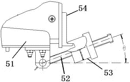
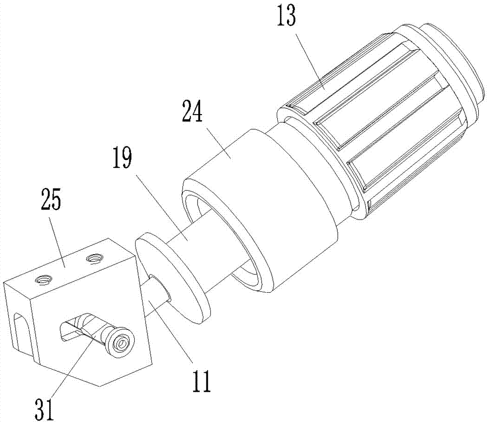
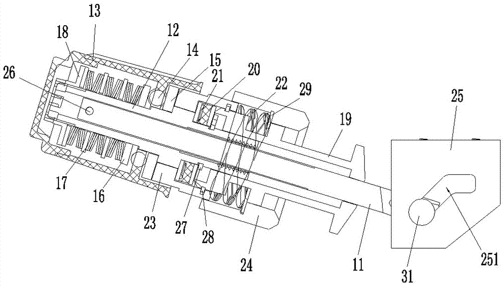
[0023] Examples of pull-out latches for enclosures, such as Figure 2-12 As shown, the booster lock includes a lock rod 11, a screw sleeve 12, a screw cap 13, a transmission steel ball 14, a transmission piece 15, a pressing piece 16, a force limiting spring 17, a spring support sleeve 18, an output sleeve 19, a transmission Seat 20, ball 21, pushing spring 22, drive sleeve 23, lock cap 24 and lock seat 25.

[0024] The front end of the locking rod 11 is provided with a hinge hole and a threaded section is provided between the two ends.

[0025] The position between the two ends of the screw sleeve 12 is provided with an internal thread segment, which corresponds to the thread segment on the lock bar 11, and the screw sleeve 12 is exactly through the connection between its internal thread segment and the thread segment of the lock bar 11. Cooperate and threadedly assembled on the lock rod 11, because both of them are not all provided with threads, so the rear end of the lock ...


PUM


Abstract

The invention relates to the field of modular electric cabinets, in particular to a pull-out locking device for a cabinet. The pull-out locking device for the chassis includes a lock rod and a lock cap. The front end of the lock cap is provided with a locking opening for cooperating with the locking hook on the chassis. The output sleeve is equipped with an output sleeve, and the front part of the output sleeve is provided with a hook structure for cooperating with the locking hook on the corresponding chassis to pull out the chassis backward. It is disassembled on the screw sleeve, and the rear end of the transmission sleeve is provided with an inward-turning edge, and there is a device between the screw sleeve and the inversion edge of the transmission sleeve, which can transmit the backward movement of the screw sleeve to the transmission sleeve and can Rotary transmission mechanism that rotates the screw sleeve relative to the transmission sleeve. The pulling-out locking device for the cabinet of the present invention solves the problem that the existing locking device cannot assist in pulling out the cabinet when the cabinet is removed.

Description

technical field [0001] The invention relates to the field of modular electric cabinets, in particular to a pull-out locking device for a cabinet. Background technique [0002] With the development of modularization and miniaturization of various electronic equipment, electronic equipment cabinets have been widely used in electronic equipment cabinets (electrical cabinets). In the specific use process, in order to realize the overall loading, unloading and replacement, the electronic equipment chassis is introduced through the electrical connector provided at the rear end and the adapter connector provided in the cabinet to realize the introduction of the electronic equipment chassis. It is required that the electronic equipment case must have a reliable fixing mechanism when it is assembled on the cabinet. [0003] figure 1 Shown is a common locking device used for locking electronic equipment chassis in the prior art. The locking device includes a lock base 51, a locking ...

Claims


Application Information

Patent Timeline
Patent Type & Authority Patents(China)
IPC IPC(8): H05K7/14
Inventor 周卫可吕云朋陈建超杨成博
Owner CHINA AVIATION OPTICAL-ELECTRICAL TECH CO LTD
Why Eureka
Try Eureka