
Device and method for testing residual voltage

A technology of residual voltage and testing device, applied in the direction of measuring device, testing dielectric strength, measuring current/voltage, etc., can solve the problem of inaccurate accuracy, and achieve the effect of solving inaccurate accuracy, ensuring accuracy, and reducing reading errors.

Inactive Publication Date: 2015-04-08
SGS STANDARD TECHNICAL SERVICES SHANGHAI CO LTD
View PDF5 Cites 8 Cited by
  • Summary
  • Abstract
  • Description
  • Claims
  • Application Information

AI Technical Summary

Problems solved by technology

[0005] The purpose of the present invention is to solve the above-mentioned deficiencies and provide a residual voltage testing device and its testing method. Through verification and comparison tests, the combined use of the testing device with a high-voltage high-impedance probe and an oscilloscope can effectively solve the current problems. The problem of repeated testing and insufficient precision

Method used


Image

  • Device and method for testing residual voltage
  • Device and method for testing residual voltage
  • Device and method for testing residual voltage

Examples


Embodiment Construction

[0025] Below in conjunction with accompanying drawing, the present invention will be further described as follows:

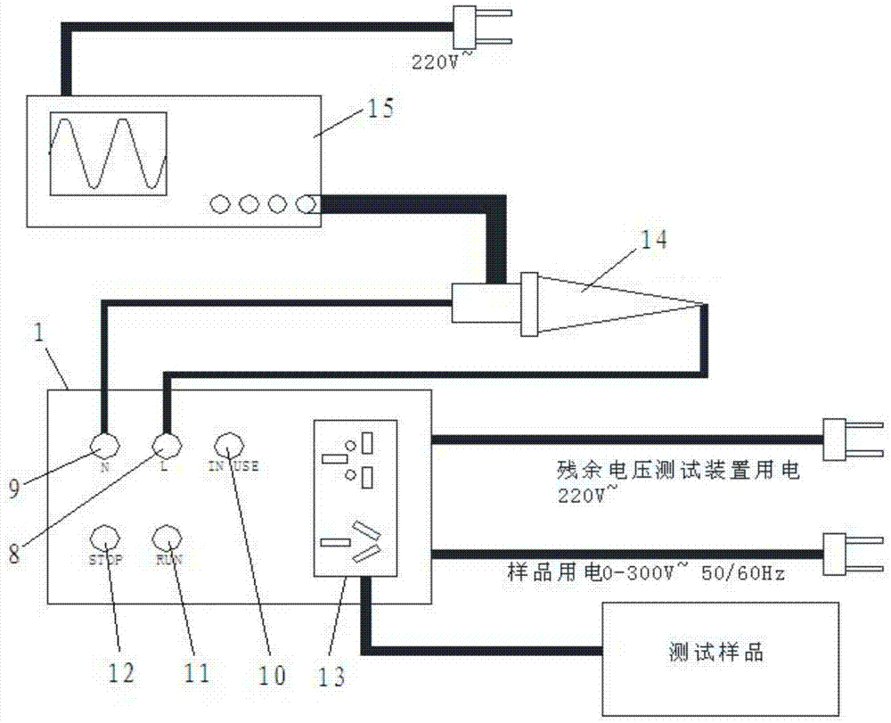
[0026] As shown in the drawings, the present invention includes: a housing 1, which is provided with an internal power supply module 2, an MCU module 3, a key input module 4, a variable frequency power input module 5, a peak voltage detection module 6 and a voltage output and Disconnect the control module 7, the output terminals of the internal power supply module 2 and the key input module 4 are respectively connected to the MCU module 3, the MCU module 3 is connected to the peak voltage detection module 6, and the input terminal of the peak voltage detection module 6 is connected to the variable frequency power supply input module 5, The output terminal of the peak voltage detection module 6 is connected to the voltage output and disconnection control module 7, and the front of the housing 1 is provided with an L input terminal 8, an N input terminal 9, a use s...


PUM


Abstract

The invention relates to a device and a method for testing residual voltage. The device comprises a shell (1), wherein an internal power supply module (2), an MCU (Micro Control Unit) module (3), a key input module (4), a variable-frequency power input module (5), a peak voltage detection module (6) and a voltage output and turn-off control module (7) are arranged in the shell (1); the output ends of the internal power supply module (2) and the key input module (4) are connected with the MCU module (3) respectively; the MCU module (3) is connected with the peak voltage detection module (6); the input end of the peak voltage detection module (6) is connected with the variable-frequency power input module (5); the output end of the peak voltage detection module (6) is connected with the voltage output and turn-off control module (7). Compared with the prior art, the device for testing the residual voltage has the advantages that by virtue of verification and comparison tests, the device is combined with a high-voltage high-impedance probe and an oscilloscope for use, so that the problems of repeated testing and low accuracy in the prior art can be quite effectively solved.

Description

[technical field] [0001] The invention relates to the technical field of electronic and electrical equipment testing devices, in particular to a residual voltage testing device and a testing method thereof. [Background technique] [0002] For the medical device standard IEC 60601-1:2005 general standard, Chapter 8.4.3 ME EQUIPMENT intended to be connected to a power source by a plug& Chapter 8.4.4 Internal capacitive circuits (internal capacitor circuit), or the medical device standard IEC Chapter 15 voltage and (or) energy limits in 60601-1:1988, and the relevant clauses of 60950 are tested. [0003] At present, for the plug discharge test, the conventional method is to achieve the test purpose by connecting the oscilloscope to measure the residual voltage after the tester mechanically pulls out the plug. There are two disadvantages in this method: first, the connection time between the plug and the oscilloscope is usually longer than one second; second, it cannot effectiv...

Claims


Application Information

Patent Timeline
IPC IPC(8): G01R19/00G01R31/12
Inventor 尹勇孙大光孟志敏赵扬
Owner SGS STANDARD TECHNICAL SERVICES SHANGHAI CO LTD
Learn More