Al technical title is built by PatSnap Al team. It summarizes the technical point description of the patent document.
A testing device and oil film technology, which is applied in the testing of machine gears/transmission mechanisms, etc., can solve problems such as excessive adjustment clearance, difficulty in ensuring accuracy, and slow progress in experimental research, and achieve uniform oil film thickness, good centering, and torque transmission stable effect
Inactive Publication Date: 2015-04-08
JIANGSU UNIV
View PDF12 Cites 8 Cited by
Summary
Abstract
Description
Claims
Application Information
AI Technical Summary
This helps you quickly interpret patents by identifying the three key elements:
Problems solved by technology
Method used
Benefits of technology
Problems solved by technology
At present, the theoretical research on liquid viscous transmission technology has achieved considerable results, but the progress in experimental research has been slow, mainly because of the lack of test devices that are easy to operate, simple in structure, and easy to detect.
Previously, CN103790998A had disclosed a double-plate fluid-viscous speed-regulating clutch, which manually adjusted the thickness of the oil film between the active and passive plates through fine threads, and adjusted the power output of the oil film. However, the adjustable range of the oil film thickness was too small. The adjustment gap is too large, the accuracy is difficult to guarantee, and the internal oil film flow state is invisible, etc.
Method used
Image
Click on the blue label to locate the original text in one second.
Reading with bidirectional positioning of images and text.
Examples
Embodiment Construction
[0020] The present invention will be described in further detail below in conjunction with the accompanying drawings.
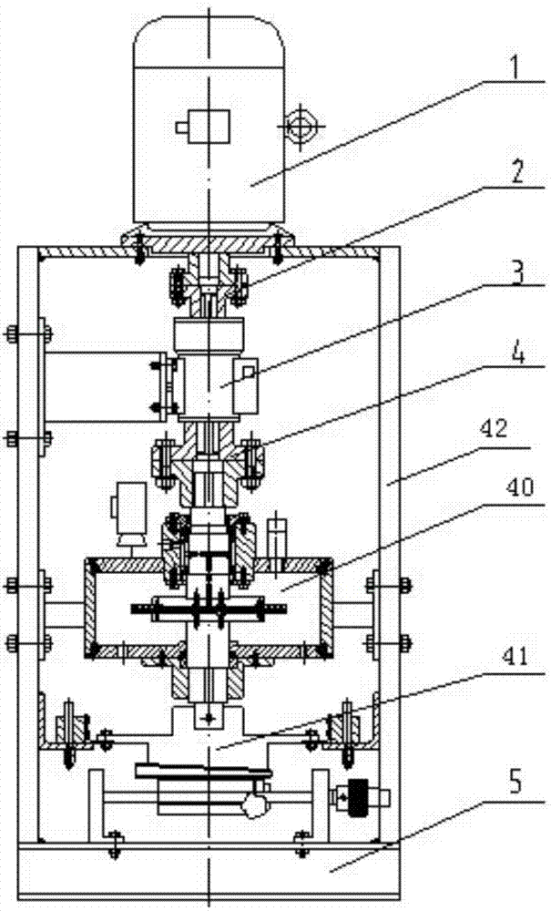
[0021] A vertical visual oil film power test device mainly includes a driving force part, a liquid viscous main engine, an oil film thickness adjustment device, a support, and the like.
[0022] The motive force part mainly includes a motor, a first shaft coupling, a torque tachometer, a second shaft coupling, an input shaft of a hydraulic viscous main engine, and the like. The output end of the motor is connected to the input end of the torque tachometer through the first coupling, and the output end of the torque tachometer is connected to the input shaft of the hydraulic viscose main engine through the second coupling.
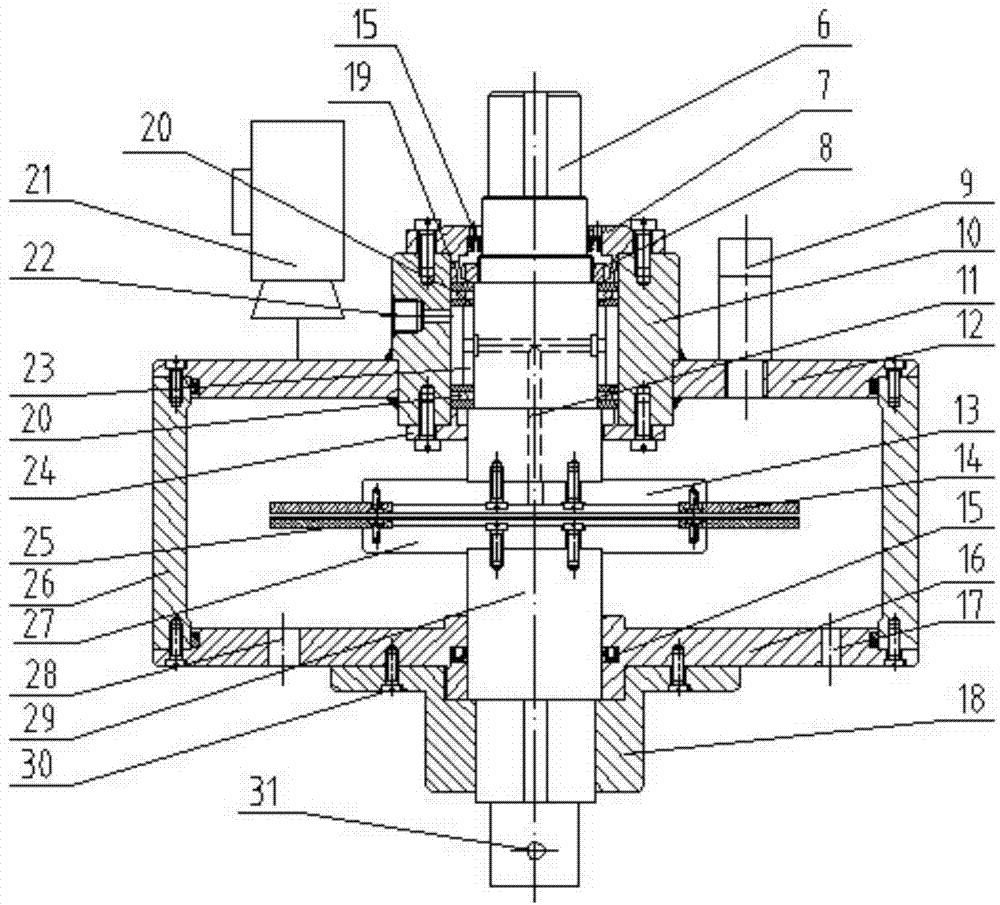
[0023] The liquid viscous main engine mainly includes an input shaft, an upper end cover of a bearing, a lock nut, a sleeve, a sleeve stopper, a plane thrust bearing, a bearing stopper, an upper case cover, an active plate support, an acti...
PUM
Abstract
The invention discloses a vertical visual oil film power test device, which mainly comprises a prime power part, a liquid viscosity host machine, an oil film thickness regulating device, a support seat and the like, wherein an upper box cover, a lower box cover and a support plate of the liquid viscosity host machine are connected through screws to form a liquid viscosity host machine case, a sleeve passes through the upper box cover and is fixed with the upper box cover through welding, an input shaft passes through the sleeve to be connected with a driving sheet support seat, a driving friction sheet is fixedly arranged on the driving sheet support seat, a driven friction sheet is fixedly arranged on a driven sheet support seat, the driven sheet support seat is connected with an output shaft, the output shaft is connected with an output shaft fixing stop block and is fixedly arranged on the lower box cover, the output shaft is maintained not to rotate, meanwhile, the output shaft is fixed with a groove block through a pin post, the groove block is arranged on a wedge-shaped slide block, the wedge-shaped slide block moves through regulating a lead screw, and the ascending and the descending of the output shaft in the vertical direction are realized. The vertical visual oil film power test device has the advantages that the operation is convenient, the structure is simple, the detection is easy, and the functions of wide-range oil film thickness regulation, fine regulation, visible oil film flow state and the like can be realized.
Description
technical field [0001] The invention relates to a testing device, in particular to a vertical visual oil film dynamic testing device. technical background [0002] With the development of society, energy saving and consumption reduction have become a topic of common concern. The introduction of fluid viscous speed clutches into the soft start and speed regulation process of large mechanical equipment can greatly reduce equipment energy consumption and improve equipment working stability. [0003] The hydraulic viscous clutch is a device developed by applying liquid viscous transmission technology. It is a transmission device that uses liquid as the working medium and adjusts the output speed and torque by changing the thickness of the oil film between the friction pairs. . At present, considerable achievements have been made in theoretical research on liquid viscous transmission technology, but progress in experimental research is slow, mainly because of the lack of test de...
Claims
Application Information
Patent Timeline
Application Date:The date an application was filed.
Publication Date:The date a patent or application was officially published.
First Publication Date:The earliest publication date of a patent with the same application number.
Issue Date:Publication date of the patent grant document.
PCT Entry Date:The Entry date of PCT National Phase.
Estimated Expiry Date:The statutory expiry date of a patent right according to the Patent Law, and it is the longest term of protection that the patent right can achieve without the termination of the patent right due to other reasons(Term extension factor has been taken into account ).
Invalid Date:Actual expiry date is based on effective date or publication date of legal transaction data of invalid patent.