Ultrasonic-based small-range liquid level measuring device and measuring method
A liquid level measuring device and ultrasonic technology, which are applied in the direction of measuring device, liquid/fluid solid measurement, lubrication indicating device, etc. limited issues
- Summary
- Abstract
- Description
- Claims
- Application Information
AI Technical Summary
Problems solved by technology
Method used
Image

Examples
Embodiment 1
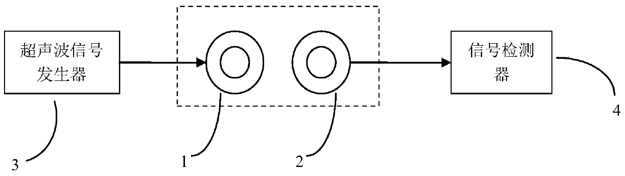
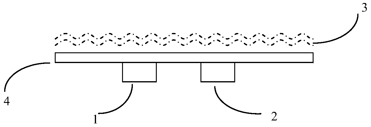
[0035] According to the working principle of the present invention figure 1 and implement device placement profile figure 2 The distance between the circular piezoelectric ceramic sheet 1 for transmitting ultrasonic waves and the circular piezoelectric ceramic sheet 2 for receiving ultrasonic waves is 3 cm, and the two specifications are the same and completely matched, according to figure 2 Schematic installation, the piezoelectric ceramic sheet 1 for emitting ultrasonic waves and the circular piezoelectric ceramic sheet 2 for receiving ultrasonic waves are fixed at the center of the substrate, and the sensor is placed at the bottom of the liquid. The metal surfaces of the two piezoelectric ceramic sheets are exposed to ensure contact with the measured liquid, and the rest are sealed to ensure the insulation of the ultrasonic generator and receiver leads. The piezoelectric ceramic sheet 1 is connected with the ultrasonic signal generator through the lead wire, and the circ...
Embodiment 2
[0037] according to figure 2Schematic diagram of installation, the distance between the circular piezoelectric ceramic sheet 1 for transmitting ultrasonic waves and the circular piezoelectric ceramic sheet 2 for receiving ultrasonic waves is 5cm, the specifications of the two are the same and completely matched, and the rest are the same as the specific embodiment 1. The circular piezoelectric ceramic sheet The electric ceramic sheet 1 and the circular piezoelectric ceramic sheet 2 are fixed at the center of the substrate, and the sensor is placed at the bottom of the liquid. The metal surfaces of the two piezoelectric ceramic sheets are exposed to ensure contact with the measured liquid, and the rest are sealed to ensure the insulation of the ultrasonic generator and receiver leads. The piezoelectric ceramic sheet 1 is connected with the ultrasonic signal generator through the lead wire, and the circular piezoelectric ceramic sheet 2 is connected with the signal detector thr...
Embodiment 3
[0039] according to figure 2 Schematic diagram of installation, the distance between the circular piezoelectric ceramic sheet 1 for transmitting ultrasonic waves and the circular piezoelectric ceramic sheet 2 for receiving ultrasonic waves is 3 cm. The specifications and resonant frequencies of the two are different, and the rest are the same as in the first embodiment. The shaped piezoelectric ceramic sheet 1 and the circular piezoelectric ceramic sheet 2 are fixed at the center of the substrate, and the sensor is placed at the bottom of the liquid. The metal surfaces of the two piezoelectric ceramic sheets are exposed to ensure contact with the measured liquid, and the rest are sealed to ensure the insulation of the ultrasonic generator and receiver leads. The piezoelectric ceramic sheet 1 is connected with the ultrasonic signal generator through the lead wire, and the circular piezoelectric ceramic sheet 2 is connected with the signal detector through the lead wire. Compa...
PUM
 Abstract
Description
Claims
Application Information
 - Generate Ideas
- Intellectual Property
- Life Sciences
- Materials
- Tech Scout
- Unparalleled Data Quality
- Higher Quality Content
- 60% Fewer Hallucinations
Browse by: Latest US Patents, China's latest patents, Technical Efficacy Thesaurus, Application Domain, Technology Topic, Popular Technical Reports.
© 2025 PatSnap. All rights reserved.Legal|Privacy policy|Modern Slavery Act Transparency Statement|Sitemap|About US| Contact US: help@patsnap.com