
Device and method for hydraulic structure deformation distribution type optical fiber monitoring

A technology of distributed optical fiber and monitoring device, which is applied to measurement devices, optical devices, instruments, etc., can solve problems such as poor durability, difficult circuit setting, and difficult construction and layout, so as to improve reliability and engineering practicability and reduce engineering costs. Monitoring and testing costs, the effect of facilitating project transportation and use

Active Publication Date: 2015-04-08
HOHAI UNIV
View PDF7 Cites 9 Cited by
  • Summary
  • Abstract
  • Description
  • Claims
  • Application Information

AI Technical Summary

Problems solved by technology

[0003] At present, conventional hydraulic structure deformation monitoring devices have many shortcomings such as difficult construction and layout, low reusability, difficult maintenance, poor durability, low precision, and susceptibility to electromagnetic environment interference.
Optical fiber sensors have the characteristics of radiation resistance and corrosion resistance, and have obvious advantages in the monitoring of uneven deformation and disease. However, from the current situation of optical fiber deformation monitoring, distributed real-time monitoring methods are current research and application hotspots, but the technology itself and engineering The practicability is still immature. Using the changes of Rayleigh scattering, Fresnel reflection and Brillouin scattering in the optical fiber, not only can the inhomogeneous deformation be accurately located theoretically, but also a quantitative description of the inhomogeneous deformation can be given; but In the process of realizing the above goals, the laying of optical fibers is extremely sophisticated, especially the loop setting is even more difficult
From the perspective of the latest optical fiber technology field, the ODiSI (Optical Distributed Sensor Interrogator) distributed optical fiber sensing system of Luna Technology Company in the United States can achieve mm-level spatial resolution, but the maximum sensing length is only 50m, and it is affected by many factors in practical applications. Interference, the effective monitoring length and resolution will be reduced; the photonometer produced by Japan NBX company using PPP-BOTDA technology can improve the effective spatial resolution to cm level, but it requires the layout of optical fiber loops, making it difficult to be directly applied in practice Engineering uneven deformation monitoring

Method used


Image

  • Device and method for hydraulic structure deformation distribution type optical fiber monitoring
  • Device and method for hydraulic structure deformation distribution type optical fiber monitoring
  • Device and method for hydraulic structure deformation distribution type optical fiber monitoring

Examples


Embodiment Construction

[0022] The present invention will be further described below in conjunction with the accompanying drawings.

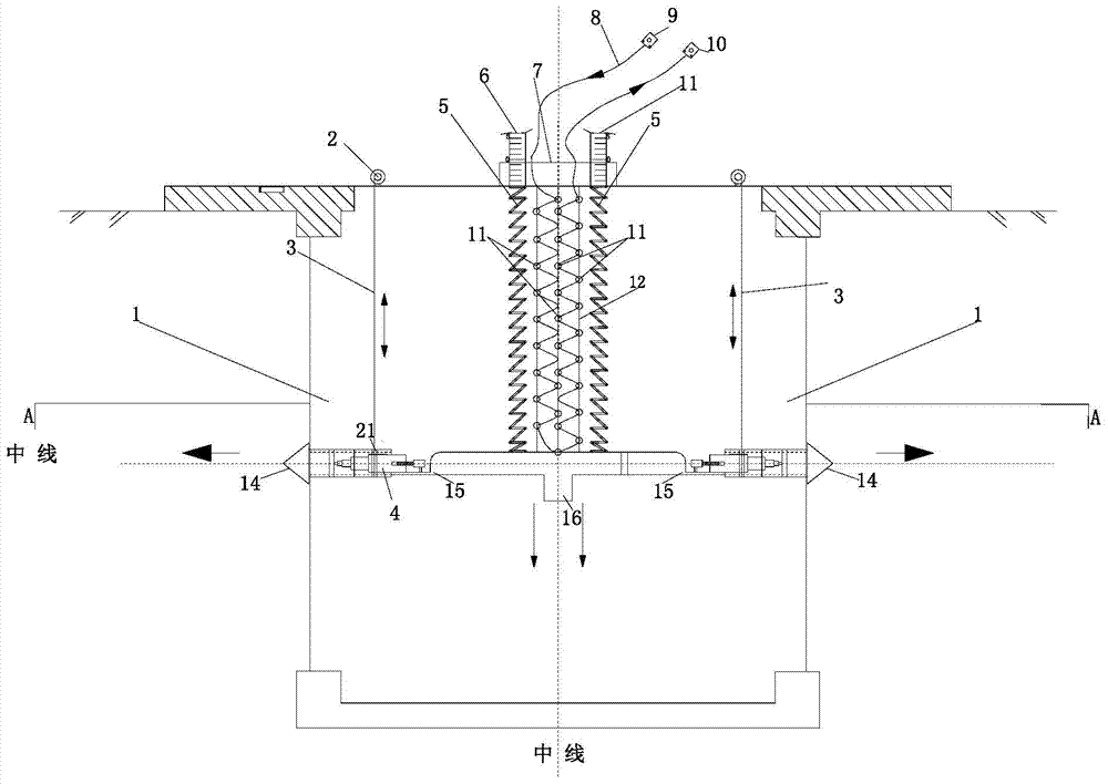
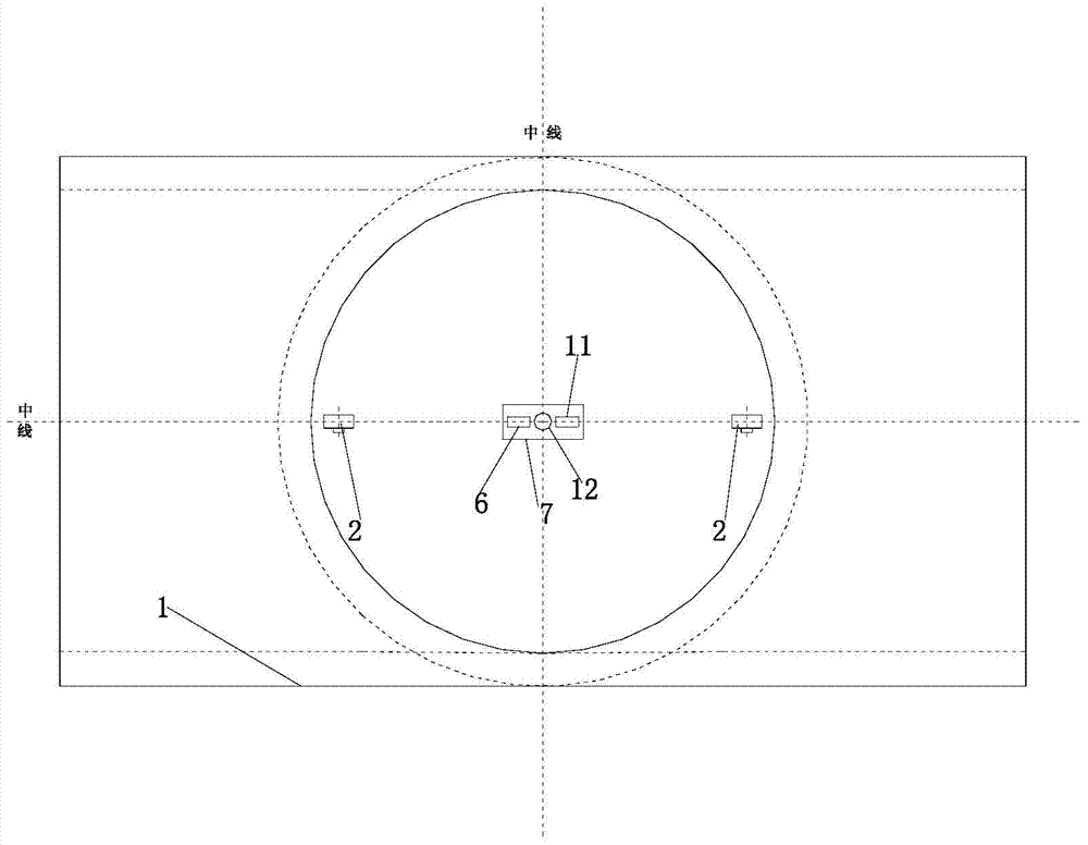
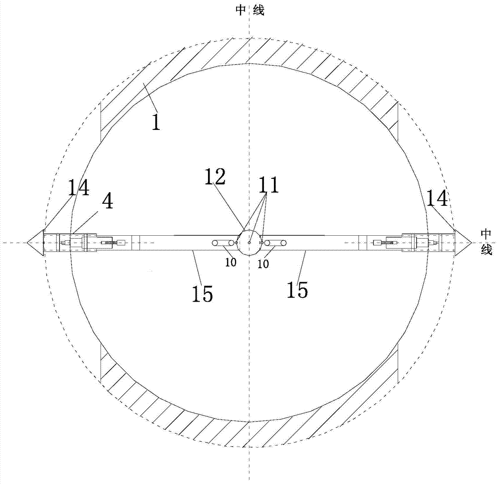
[0023] Such as Figure 1 to Figure 4 As shown, a distributed optical fiber monitoring device for hydraulic structure deformation of the present invention includes a bottom-through shaft 1, a shifting table 15 is installed in the bottom-through shaft 1, and two sides of the shifting table 15 are symmetrically installed with The drill drive device 4 is connected with the tapered drill bit 14; the drill drive device 4 on both sides of the shifting table 15 is respectively connected with the lifting rope 3, and the lifting rope 3 is wound on the take-up reel, and the take-up reel is installed on the gear On the shaft 2, the gear on the gear shaft 2 meshes with the rotating gear, and the rotating gear is driven by a motor; the middle part of the shifting table 15 is connected with one end of a pair of symmetrically installed springs, and the other end of the spring is hinge...


PUM


Abstract

The invention discloses a device and a method for hydraulic structure deformation distribution type optical fiber monitoring. The device comprises a through-bottom vertical shaft, wherein a displacement platform is arranged in the through-bottom vertical shaft, drill bit driving devices are arranged at the two sides of the displacement platform, are connected with conical drill bits, and are respectively connected with lifting ropes, the lifting ropes are wound around coiling discs, the middle part of the displacement platform is connected with one end of each of a pair of springs, the other end of each of the pair of springs is hinged to a vertical measuring ruler, the vertical measuring ruler penetrates through a scale platform, an optical fiber hanging bucket is arranged between the two springs, a wavy loop optical fiber is arranged in the optical fiber hanging bucket, an optical fiber buckle is arranged on the wavy loop optical fiber, an optical wave transmitter is arranged at the input end of the wavy loop optical fiber, and an optical wave collector is arranged at the output end of the wavy loop optical fiber. The device has the advantages and characteristics that the repeated use is realized, the installation is very convenient, the real-time detection and maintenance are realized, the distributed type structure is realized, the micro and macro effect and real-time effect are realized, the suitability to complex environment is high, and the like.

Description

technical field [0001] The invention relates to a monitoring method of a distributed optical fiber monitoring device for hydraulic structure deformation, which belongs to the field of construction. Background technique [0002] During the operation of hydraulic structures such as embankments and sluices, problems such as uneven settlement often occur, which adversely affect the safety and normal use of buildings, and even lead to building damage or accidents. By arranging monitoring instruments or devices, real-time acquisition of regional deformation information, reasonable analysis of regional deformation space and time variation rules, timely detection of abnormal regional deformation (especially uneven deformation), and scientifically taking preventive or control measures are necessary to ensure the protection of hydraulic structures. Material safety service is of great significance. [0003] At present, conventional hydraulic structure deformation monitoring devices ha...

Claims


Application Information

Patent Timeline
Patent Type & Authority Applications(China)
IPC IPC(8): G01B11/16
Inventor 苏怀智杨孟李皓李星欧斌
Owner HOHAI UNIV
Learn More