
A ten-speed hydraulic transmission for a vehicle

A technology of hydraulic transmission and hydraulic torque converter, which is applied in the field of mechanical transmission, can solve the problems of complex structure of hydraulic transmission device, large volume and weight of the whole machine, and influence on the quality of vehicle shifting, so as to broaden the range of efficacy, The ratio is reasonable and the effect of improving the smoothness of shifting

Active Publication Date: 2017-01-25
贵州凯星液力传动机械有限公司
View PDF4 Cites 0 Cited by
  • Summary
  • Abstract
  • Description
  • Claims
  • Application Information

AI Technical Summary

Problems solved by technology

For example, in order to increase the speed of movement in a low-load state, many walking construction machinery equipment requires an overdrive gear with a smaller transmission ratio when the engine performance remains unchanged, while the traditional hydraulic transmission with six forward gears The device has only one overspeed gear, and the transmission ratio is relatively large, which cannot meet the needs of actual work
[0003] The number of available forward speed ratios in a hydraulic transmission determines the number of repetitions of the engine torque range. Traditional vehicle hydraulic transmissions have only six forward gears at most, and the ratio steps between speed ratios are large, making it difficult to fuel consumption. It is close to the most effective point, the fuel economy is poor, and it also affects the shifting quality of the vehicle; secondly, the structure of this hydraulic transmission device is complex, the two rotating clutches adopt a series structure, and the oil pump assembly adopts an external arrangement The method makes the volume and weight of the whole machine larger, which can no longer meet the requirements of miniaturization of hydraulic transmission devices in modern operating equipment.

Method used


Image

  • A ten-speed hydraulic transmission for a vehicle
  • A ten-speed hydraulic transmission for a vehicle

Examples


Embodiment Construction

[0022] The technical solution of the present invention is further described below in conjunction with the accompanying drawings, but the scope of protection is not limited to the description.

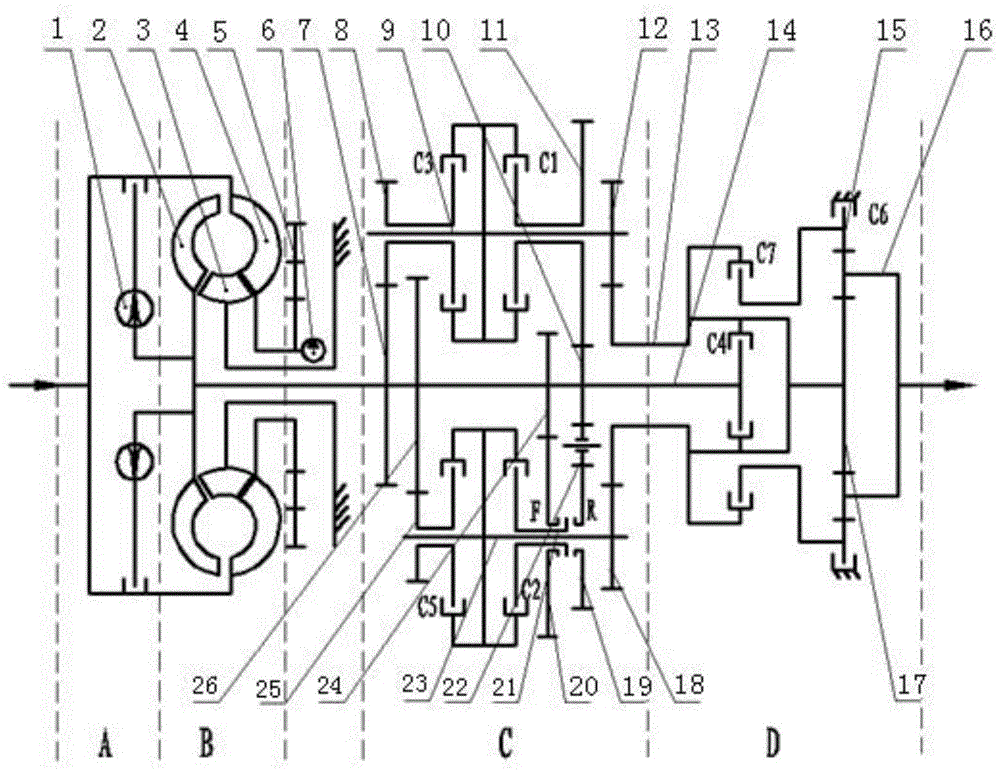
[0023] Such as figure 1 As shown, a ten-speed hydraulic transmission for a vehicle according to the present invention includes a power output device 5, a lock-up and damping clutch assembly A, a hydraulic torque converter B, a main shaft 14, a main gearbox C, an auxiliary transmission Box D, the first parallel shaft 9 and the second parallel shaft 23, the output end of the power output device 5 is connected to the locking and damping clutch assembly A through the hydraulic torque converter B, and the locking and damping clutch assembly A is connected with the main shaft 14, and the main shaft 14 is connected with the main gearbox C and the auxiliary gearbox D at the same time; in the main gearbox C, the main shaft gear 1 7, the main shaft gear 2 26, the main shaft gear Three 24 and mai...


PUM


Abstract

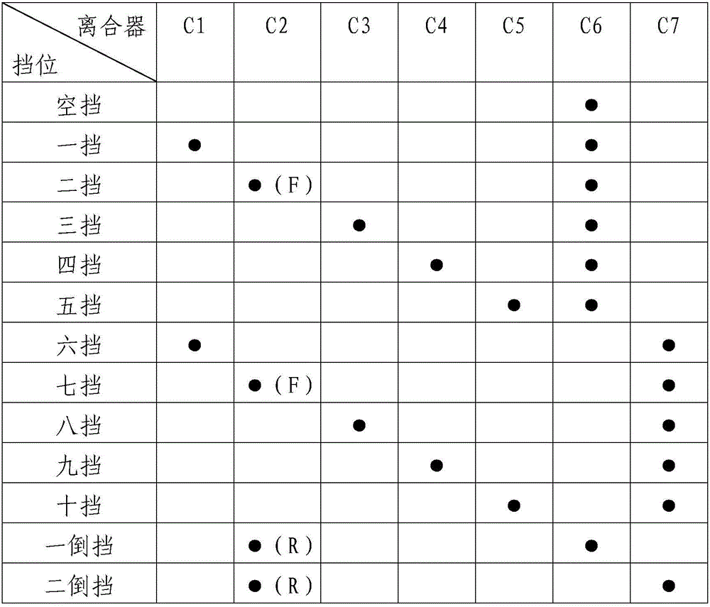
The invention discloses a ten-speed hydraulic transmission for vehicles, which belongs to the technical field of mechanical transmission and includes a power output device, a locking and damping clutch assembly, a hydraulic torque converter, a main shaft, a main gearbox, an auxiliary gearbox, a second A parallel shaft and a second parallel shaft, the output end of the power output device is connected to the locking and damping clutch assembly through the hydraulic torque converter, the locking and damping clutch assembly is connected to the main shaft, and the main shaft is simultaneously Connect with main gearbox and auxiliary gearbox. This technical solution provides ten forward gears and two reverse gears with speed and torque output by controlling the power transmission route by seven torque transmission devices, and increases the optional range of transmission ratio; by using a built-in gear pump, The space of the hydraulic transmission is effectively saved, the structure of the transmission is simplified, the structure of the transmission is made more compact, and the weight of the whole transmission is reduced.

Description

technical field [0001] The invention belongs to the technical field of mechanical transmission, and relates to a multi-speed hydraulic transmission combined with parallel shaft transmission and planetary transmission, in particular to a ten-speed hydraulic transmission for vehicles. Background technique [0002] The transmission device of the planetary hydraulic transmission is generally composed of a hydraulic torque converter and a mechanical planetary gear box. It is characterized by coaxial transmission and is suitable for machines with coaxial arrangement and one-way output. High power density per unit volume, suitable for high-power machinery and machinery and vehicles that require compact layout. However, due to structural limitations, the planetary hydraulic transmission consumes a lot of fuel at the start, has a complex structure and has fewer gears, and cannot realize gear jumping. With the development of technology and the improvement of vehicle driving requireme...

Claims


Application Information

Patent Timeline
Patent Type & Authority Patents(China)
IPC IPC(8): F16H47/08F16H57/023
CPCF16H47/08F16H57/023
Inventor 王辉李晓东李世鹏罗静马晨启
Owner 贵州凯星液力传动机械有限公司
Learn More