Kick type vibration absorbing method and kick type vibration absorber
A technology of recoil type and shock absorber, which is applied in the direction of spring/shock absorber, vibration suppression adjustment, non-rotational vibration suppression, etc. It can solve the problems of increasing self-weight, difficulty in achieving the desired effect, and difficulty in adapting to vehicles, etc., to achieve The effect of eliminating vibration and completely eliminating vibration
- Summary
- Abstract
- Description
- Claims
- Application Information
AI Technical Summary
Problems solved by technology
Method used
Image
Examples
Embodiment 1
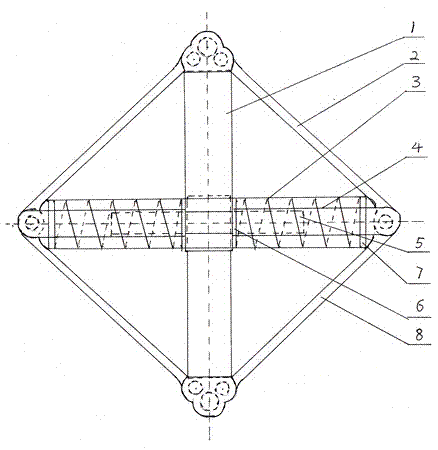
[0020] Such as figure 1 As shown, the recoil type vibration absorber is a direct-reverse type vibration absorber, which is mainly composed of a positioning assembly 1, an upper connecting rod 2, a lower connecting rod 8 and a buffer spring 3. The upper connecting rod 2 and The lower connecting rods 8 are arranged symmetrically and connected to each other in a rhombus shape; the upper connecting rod 2 is composed of an upper connecting head and connecting rods arranged on both sides of the upper connecting head. One end of the connecting rod is fixed on the upper connecting head, and the connecting rod The rod can rotate along a fixed position; the lower connecting rod 8 is composed of a lower connecting head and connecting rods arranged on both sides of the lower connecting head. One end of the connecting rod is fixed on the lower connecting head, and the connecting rod can rotate along a fixed position; The two connecting rods of the connecting rod 2 and the two connecting rods...
Embodiment 2
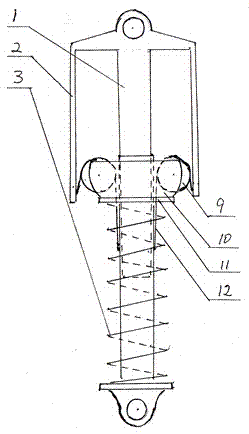
[0025] Such as figure 2 As shown, the recoil type vibration absorber is a foldback type vibration absorber. The above foldback type vibration absorber is mainly composed of a positioning assembly 1, an upper connecting rod 2 and a buffer spring 3. The upper connecting rod 2 is in an inverted U shape, and the positioning assembly The upper end of the component 1 is fixed at the center of the upper link 2.
[0026] The positioning assembly 1 is composed of a fixed rod and a sleeve rod. The top end of the fixed rod is fixed on the upper connecting rod 2, the sleeve rod is sleeved on the outside of the fixed rod, and the buffer spring 3 is sleeved on the outer side of the sleeve rod and above the buffer spring 3. An upper clamping seat 11 is provided. The upper clamping seat 11 is sleeved on the outside of the sleeve rod and can slide up and down along the sleeve rod. A folding wheel seat 10 is also provided on the upper clamping seat 11, and the folding wheel seat 10 is also symmet...
Embodiment 3
[0029] The difference between this embodiment and the second embodiment is that the turn-back wheel is replaced by turn-back gear teeth, and a rack that meshes with the turn-back gear teeth is provided on the inner side of the upper link and the sleeve rod of the positioning assembly.
PUM
 Abstract
Description
Claims
Application Information
 - R&D
- Intellectual Property
- Life Sciences
- Materials
- Tech Scout
- Unparalleled Data Quality
- Higher Quality Content
- 60% Fewer Hallucinations
Browse by: Latest US Patents, China's latest patents, Technical Efficacy Thesaurus, Application Domain, Technology Topic, Popular Technical Reports.
© 2025 PatSnap. All rights reserved.Legal|Privacy policy|Modern Slavery Act Transparency Statement|Sitemap|About US| Contact US: help@patsnap.com


