
Oil-gas separator

A technology of oil-gas separator and mixed gas, which is applied in the direction of machine/engine, engine components, mechanical equipment, etc., can solve the problems of complex structure, high manufacturing cost, low separation efficiency, etc., to simplify the engine structure, prevent icing, improve The effect of separation efficiency

Inactive Publication Date: 2015-04-08
BRILLIANCE AUTO
View PDF6 Cites 10 Cited by
  • Summary
  • Abstract
  • Description
  • Claims
  • Application Information

AI Technical Summary

Problems solved by technology

[0004] The purpose of the present invention is to provide an oil-gas separator, which fundamentally solves the problems of poor separation effect, high manufacturing cost, low separation efficiency and complicated structure of the existing oil-gas separator.

Method used


Image

  • Oil-gas separator
  • Oil-gas separator

Examples


Embodiment Construction

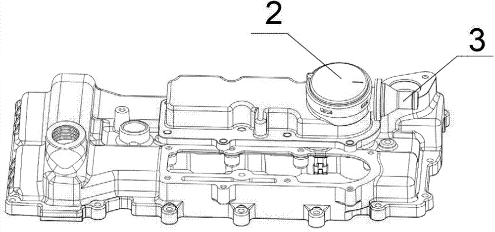
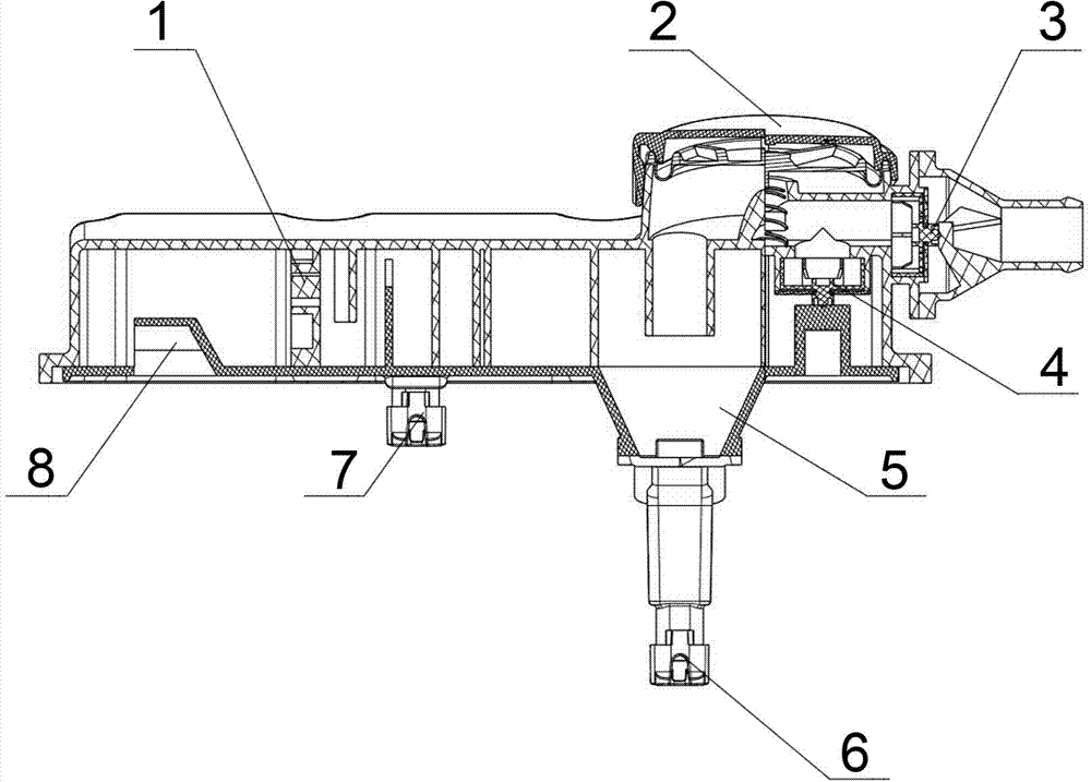
[0011] The following combination Figure 1~2 , the content of the present invention will be described in detail through specific embodiments. The oil-gas separator includes a housing installed on the valve chamber cover, an S-shaped mixed gas passage arranged in the housing, a labyrinth structure 1 and a cyclone structure 5 arranged in the housing. The mixed gas inlet of the mixed gas channel is located at the bottom of one end of the housing, the mixed gas inlet 8 is provided with a block structure, the labyrinth structure 1 is located between the mixed gas inlet and the mixed gas channel, and the cyclone structure 5 is located at the end of the mixed gas channel. Oil return control valves I 6 and II 7 are respectively provided at the bottom of the air passage and the bottom of the cyclone structure 5 , and check valves I 3 , 1 4 and PCV valve 2 are respectively provided at the exhaust end of the cyclone structure.


PUM


Abstract

An oil-gas separator comprises a shell, an S-shaped mixed gas channel, a maze structure and a cyclone structure. The shell is mounted on a cylinder head cover and internally provided with the S-shaped mixed gas channel. The maze structure and the cyclone structure are arranged in the shell. The technical scheme includes that a mixed gas inlet of the mixed gas channel is formed in the bottom of one end of the shell, a retainer platform structure is arranged at the mixed gas inlet, the maze structure is arranged between the mixed gas inlet and the mixed gas channel, the cyclone structure is arranged at the tail of the mixed gas channel, oil return control valves are arranged at the bottoms of the mixed gas channel and the cyclone structure, and a gas exhaust end of the cyclone structure is provided with a one-way valve and a PCV (positive crankcase ventilation) valve. In this way, the problems of the conventional oil-gas separator such as poor separating effect, high production cost, low separating efficiency and complicated structure are thoroughly solved.

Description

technical field [0001] The invention relates to the field of internal combustion engines, in particular to an engine component, in particular to a multifunctional, integrated and high-efficiency oil-gas separator. Background technique [0002] At present, in the automobile manufacturing, internal combustion engine and other mechanical industries, the oil-gas separator is mainly used to separate the oil from the oil-air mixture in the crankcase of the internal combustion engine, so as to reduce oil consumption and environmental pollution. More and more stringent, low-efficiency oil-gas separator with a single structure can no longer meet the requirements. The separated engine oil returns to the oil pan mainly through the following methods: 1. Directly drips into the crankcase through the oil return hole and then returns to the oil pan, but the mixed gas in the crankcase will enter the oil-gas separator through the oil return hole, Thus affecting the separation efficiency; 2....

Claims


Application Information

Patent Timeline
Patent Type & Authority Applications(China)
IPC IPC(8): F01M13/04
CPCF01M13/04F01M2013/0433F01M2013/0461
Inventor 宫晓娥黄昌瑞李振华孙洪岭
Owner BRILLIANCE AUTO
Learn More