Exhaust valve for hydraulic support

A technology of hydraulic support and exhaust valve, which is applied to mine roof supports, pillars/supports, mining equipment, etc., can solve the problems of inability to eliminate residual pressure and large risk factor, and achieve the effect of eliminating risk factor and residual pressure.

Inactive Publication Date: 2015-04-08
CHINA COAL BEIJING COAL MINING MACHINERY
View PDF6 Cites 0 Cited by
  • Summary
  • Abstract
  • Description
  • Claims
  • Application Information

AI Technical Summary

Problems solved by technology

[0003] The replacement of the existing technology is to remove the spool for replacement. During the disassembly, there is residual pressure. During the replacement process, there is no way to eliminate the residual pressure. Now the replacement is maintenance workers relying on experience. In this process, the risk factor is very high.

Method used


Image

  • Exhaust valve for hydraulic support
  • Exhaust valve for hydraulic support

Examples


specific Embodiment approach

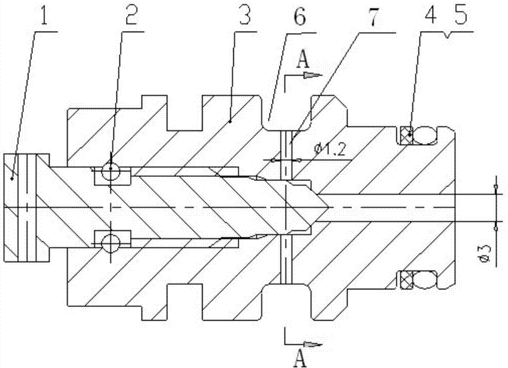
[0012] The exhaust valve for hydraulic support of the present invention, its preferred embodiment is:

[0013] It includes a joint, the joint is provided with a through hole in the axial direction, and a liquid discharge hole is provided in the radial direction. The rear part of the through hole is provided with a threaded screw rod. Sealed vice.

[0014] A limit pin is provided between the outer wall of the screw rod and the inner wall of the through hole.

[0015] The outer wall of the joint is provided with a U-shaped slot at the outlet of the drain hole.

[0016] Two φ1.2mm drain holes are radially opened on the joint, and the drain holes are perpendicular to the U-shaped slot.

[0017] The outer wall of the joint is provided with a sealing ring and a retaining ring at the front end.

[0018] The joint is made of QAL9-4 material, and the screw rod is made of high-quality stainless steel.

[0019] The exhaust valve for the hydraulic support of the present invention is u...

specific Embodiment

[0020] Such as figure 1 , figure 2 As shown, the air release valve includes a screw 1, a limit pin 2, a joint 3, a sealing ring 4 and a retaining ring 5; For sealing, put the two limit pins 2 into the joint 3, and assemble the sealing ring 4 and the retaining ring 5 on the joint 3. The rotary screw 1 is used to release the residual pressure, and at the same time, the joint 3 has a limit function, and the operation is simple and convenient.

[0021] The joint 3 adopts QAL9-4, which has a good sealing effect and a longer service life.

[0022] The positioning pin 2 prevents the screw rod 1 from being unscrewed too long, and prevents the impact from being too large.

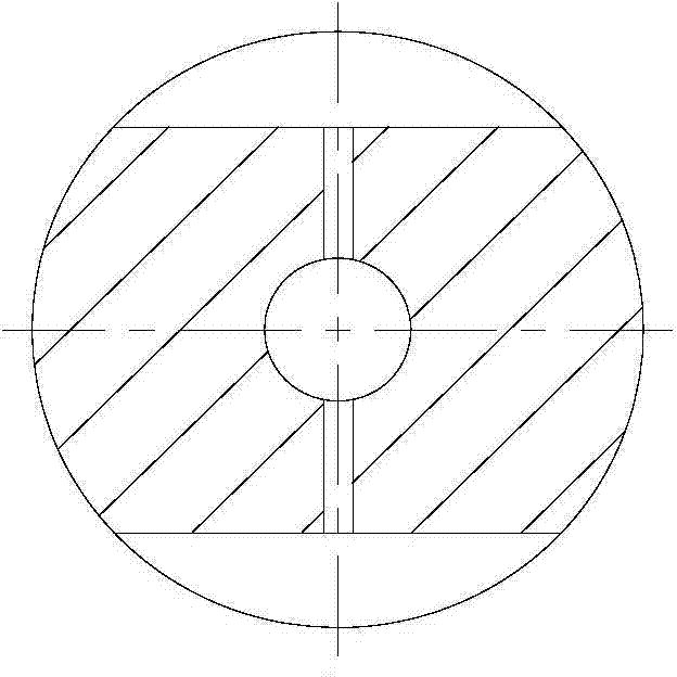
[0023] The U-shaped card on the connector 3 snaps in figure 2 The U-shaped groove on the outer wall of the connector shown prevents the connector from rotating.

[0024] Two φ1.2mm drain holes are opened on the joint 3, and the direction is perpendicular to the direction of the U-shaped slot.

[0025] The sc...


PUM


Abstract

The invention discloses an exhaust valve for a hydraulic support. The exhaust valve comprises a joint, wherein a through hole is axially formed in the joint, a drainage hole is radially formed in the joint, a screw-thread fit threaded rod is arranged at the rear part of the through hole, and a rigid sealing pair is formed by the front end of the threaded rod and the front part of the through hole; a limiting pin is arranged between the outer wall of the threaded rod and the inner wall of the through hole; a U-shaped clamping groove is formed in the outer wall of the joint at the part of an outlet of the drainage hole; a seal ring and a check ring are arranged at the front end of the outer wall of the joint. The exhaust valve plays a safety protection role on a hydraulic control valve of the hydraulic support, and a safe working environment can be provided for the changing of components and parts of a hydraulic system in the hydraulic support, so that the residual pressure in the hydraulic system is released, and the exhaust valve is convenient for workers to maintain and replace.

Description

technical field [0001] The invention relates to a hydraulic control valve for a coal mine hydraulic support, in particular to an exhaust valve for a hydraulic support. Background technique [0002] The hydraulic control valve on the hydraulic support is the core component of the hydraulic support, such as the column check valve, the balance two-way lock, the push one-way valve, etc. These are the hydraulic components that operate for a long time when the hydraulic support operates. Over time, under pressure and wear, the internal O-rings of some hydraulic control valves will be damaged and need to be replaced. [0003] The replacement of the existing technology is to remove the spool for replacement. During the disassembly, there is residual pressure. During the replacement process, there is no way to eliminate the residual pressure. Now the replacement is maintenance workers relying on experience. In this process, the risk factor is very high. . Contents of the invention...

Claims


Application Information

Patent Timeline
Patent Type & Authority Applications(China)
IPC IPC(8): E21D15/51E21D23/16
CPCE21D15/44E21D15/50
Inventor 杨树义宋冲鲁和平聂薇郑丽颖
Owner CHINA COAL BEIJING COAL MINING MACHINERY
Why Eureka
Try Eureka