Eureka AIR delivers breakthrough ideas for toughest innovation challenges, trusted by R&D personnel around the world.

Guide-in conveying tool and method of nuclear power station spent fuel framework

A technology for transportation and spent fuel, which is applied in the field of transportation for the introduction of spent fuel grids in nuclear power plants. It can solve the problems of easy rust, damage to the health of construction workers, and unfavorable protection, and achieve the effect of high work efficiency and high cleanliness

Inactive Publication Date: 2015-04-08
中广核工程有限公司 +1
View PDF5 Cites 0 Cited by
  • Summary
  • Abstract
  • Description
  • Claims
  • Application Information

AI Technical Summary

Problems solved by technology

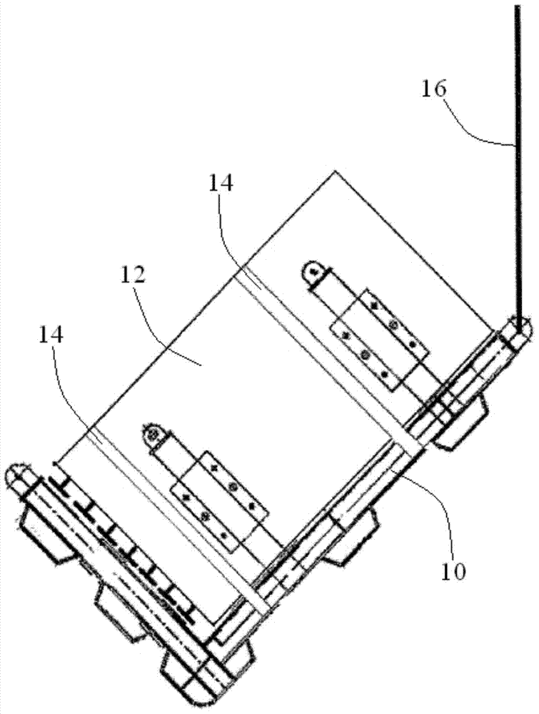
However, the above-mentioned transportation method needs to occupy the trailer all the time during the overturning process of the spent fuel grid 12, and the trailer will make the entire fuel plant + 0 meters area full of smoke and dust from automobile exhaust during the operation process, which is very important for the protection of the spent fuel grid 12. It is unfavorable, and breathing automobile exhaust for a long time will also damage the health of construction workers; especially in coastal areas, the air is humid and there are chloride ions, and the spent fuel grid 12 is extremely easy to rust after being attached by dust
[0005] In addition, the body height of the 12T trailer commonly used to transport the spent fuel grid 12 is 1500 mm, and the height of the L-shaped bracket 10 is 3893 mm. Therefore, after the L-shaped bracket 10 is installed, the overall height of the two is 5393 mm; The height of the plant door corresponding to the fuel plant +0m outer transportation channel is only 5000mm, and the available elevation is reduced to 4650mm after the gate is installed, which makes it impossible for the trailer to transport the spent fuel grid 12 into the fuel plant due to the height exceeding the standard

Method used


Image

  • Guide-in conveying tool and method of nuclear power station spent fuel framework
  • Guide-in conveying tool and method of nuclear power station spent fuel framework
  • Guide-in conveying tool and method of nuclear power station spent fuel framework

Examples


Embodiment Construction

[0029] In order to make the objectives, technical solutions and beneficial technical effects of the present invention clearer, the present invention will be further described in detail below in conjunction with the accompanying drawings and specific embodiments. It should be understood that the specific embodiments described in this specification are only for explaining the present invention, not for limiting the present invention.

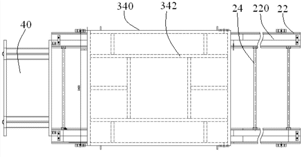
[0030] See figure 2 with image 3 , The transportation means for introducing the spent fuel grid of the nuclear power plant of the present invention includes a transportation track 20 and a transportation trolley running on the transportation track 20.

[0031] The transportation track 20 is laid on the transportation passage outside the fuel plant, and extends through the plant door to the turning platform 40 in the fuel plant. The transportation track 20 includes two monorails 22 parallel to each other and a plurality of connecting rods 24 connected...


PUM

PropertyMeasurementUnit
Heightaaaaaaaaaa
Heightaaaaaaaaaa
Heightaaaaaaaaaa

Abstract

The invention discloses a guide-in conveying tool and method of a nuclear power station spent fuel framework. The tool comprises a conveying rail and a conveying trolley operating on the conveying rail. The conveying rail is laid on a conveying passage on the outer side of a fuel building and penetrates a fuel building door to extend to a turning table in the fuel building. The conveying trolley comprises tank wheels matched with the rails and a movable conveying platform supported on the tank wheels. The method is a method for using the tool to convey the spent fuel framework into the fuel building. Compared with the prior art, the guide-in conveying tool and method has the advantages that a trailer needs not to be occupied for a long time, and the tool and method is high in cleanness and work efficiency, and the like.

Description

Technical field [0001] The present invention belongs to the field of nuclear power plant construction. More specifically, the present invention relates to a transportation tool and method for introducing spent fuel grids in nuclear power plants. Background technique [0002] In the construction of a nuclear power plant, the spent fuel grid needs to be transported into the fuel plant and then installed in the design location in the fuel pool; due to the large number of spent fuel grids, the installation cycle is in the entire fuel pool grid construction process It took a long time. [0003] See figure 1 The current spent fuel grid is transported into the fuel plant by means of L-shaped brackets and construction trailers. The specific steps are as follows: 1) Hoist the L-shaped bracket 10 to the construction trailer, and make the angled side face the direction of the front of the vehicle. In order to prevent the spent fuel grid 12 and the L-shaped bracket 10 from directly contacting...

Claims


Application Information

Patent Timeline
IPC IPC(8): B65G35/00
Inventor 王亚雄赵文灿彭杰吴伟伟胡晓飞肖思革徐剑赵培君史庆军罗大成
Owner 中广核工程有限公司
Why Eureka
Eureka Blog
Learn More