
Real dam displacement monitoring method under vibration condition

A technology of actual displacement and dynamic displacement, applied in the field of monitoring, can solve problems such as unsatisfactory requirements, lack of performance, and inability to obtain displacement, and achieve the effect of high degree of practicality, easy promotion, and high measurement accuracy.

Inactive Publication Date: 2015-04-01
NANJING NARI GROUP CORP +1
View PDF6 Cites 1 Cited by
  • Summary
  • Abstract
  • Description
  • Claims
  • Application Information

AI Technical Summary

Problems solved by technology

[0003] At present, the existing static displacement and dynamic displacement monitoring technologies cannot independently complete the monitoring task of the actual displacement of the dam under vibration conditions:
[0004] 1. Both the reference point and the reference line required by the static displacement monitoring method must remain stationary during measurement, but this requirement cannot be met under vibration conditions
In addition, in order to completely capture the displacement information at different instants in the vibration cycle, the displacement monitoring method under vibration conditions also needs to have a certain dynamic response capability (characterized by the response frequency), and the above static displacement monitoring technology does not have these aspects of performance.
[0005] 2. The monitoring method of measuring the dynamic acceleration to obtain the dynamic displacement obtains the periodic change part of the displacement during the vibration process, and cannot obtain the static part of the displacement before and after the vibration process, so the complete displacement cannot be obtained

Method used


Image

  • Real dam displacement monitoring method under vibration condition
  • Real dam displacement monitoring method under vibration condition

Examples


Embodiment Construction

[0019] In order to make the technical means, creative features, goals and effects achieved by the present invention easy to understand, the present invention will be further described below in conjunction with specific embodiments.

[0020] The terms involved in the present invention are explained as follows:

[0021] Dam displacement: The dam is not static. Under the comprehensive influence of various factors, the change of the position of each point on the dam body is the dam displacement.

[0022] Static displacement: Under normal circumstances, the displacement of the dam changes very slowly, showing static characteristics. The static displacement changes little in a short period of time, and the human senses can hardly feel it.

[0023] Dynamic displacement: The reciprocal displacement of the dam relative to the new position due to vibrations near the new position reached after the static displacement. Under the condition of vibration, the displacement of the dam is sup...


PUM


Abstract

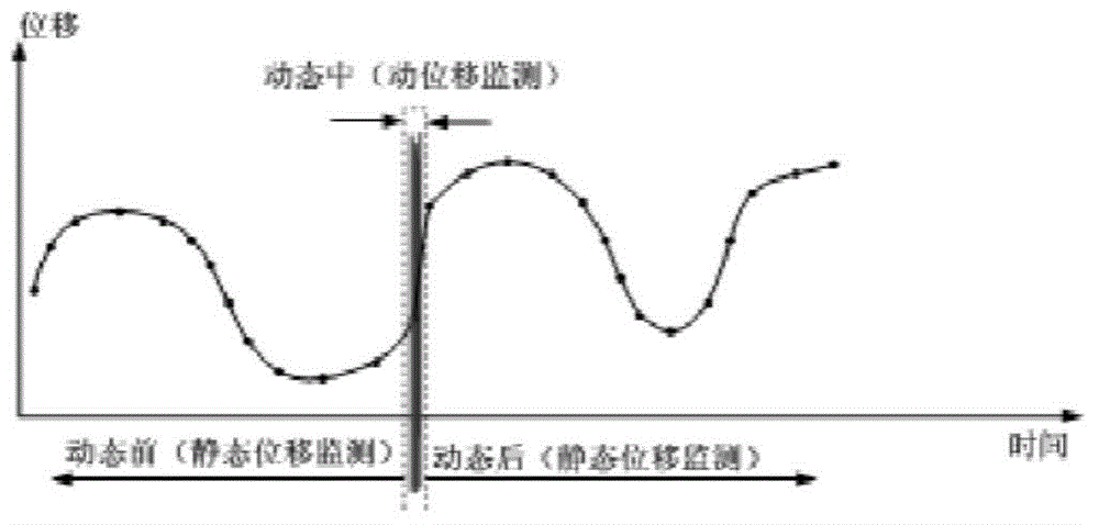
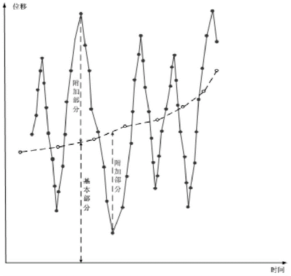
The invention discloses a real dam displacement monitoring method under the vibration condition. The method comprises steps that, (1), a static displacement monitoring method is employed to measure static dam displacement before vibration and after vibration; (2), during vibration, a dam dynamic acceleration speed is measured through a trigger acceleration gauge, and the acceleration-time function curve is drafted; as the acceleration is second differential of the displacement, second differential calculation of the acceleration-time function curve is carried out to acquire moving displacement; and (3), superposition of the last static displacement before vibration and the moving displacement is carried out to acquire the real dam displacement in the vibration process, the last real dam displacement in the vibration process is taken as the first dam static displacement after vibration, the first dam static displacement is taken as initial amount for subsequent static displacement monitoring, and thereby dam static displacement connection before and after vibration is accomplished. For hydropower stations built in earthquake-prone areas, the method combines a static displacement measurement method in the prior art and a moving displacement measurement method, can completely measure the real dam displacement in 0.1 seconds or even shorter time under the static or vibration conditions and further has properties of high measurement precision, easy popularization and high practical degree.

Description

technical field [0001] The invention relates to a monitoring method, in particular to a monitoring method for the actual displacement of a dam under vibration conditions. Background technique [0002] In the prototype monitoring of hydropower dams, the displacement of the dam body or dam foundation is a must-test monitoring item. At present, the displacement monitoring methods, means and instruments and equipment are very mature, and are widely used in various hydropower dams. However, these monitoring techniques and equipment are only limited to static, and these methods usually include: vertical line method, tension line method, static leveling method, laser alignment method, inclinometer tube method, etc. The reason is that a solid and stable displacement reference point (datum point) and a stationary measurement datum line (steel wire body, liquid surface, laser beam, etc.) are required. Once the dam is under vibration (such as earthquake) conditions, they will all los...

Claims


Application Information

Patent Timeline
IPC IPC(8): G01B21/02
CPCG01B21/02
Inventor 潘琳刘观标胡波凌骐沈慧
Owner NANJING NARI GROUP CORP
Learn More