Oil-water separation device and processing method for processing oil-containing sewage
A technology of oil-water separation device and oil-water separation membrane, which is applied in the direction of grease/oily substance/floating matter removal device, semi-permeable membrane separation, multi-stage water treatment, etc. It can solve the problem of difficult separation of heavy oil and residual oil and easy blockage of separation membrane pores , small amount of sewage treatment, etc., to achieve the effect of speeding up the washing speed, reducing the rate of residual oil deposition, and prolonging the service life
- Summary
- Abstract
- Description
- Claims
- Application Information
AI Technical Summary
Problems solved by technology
Method used
Image
Examples
Embodiment 1
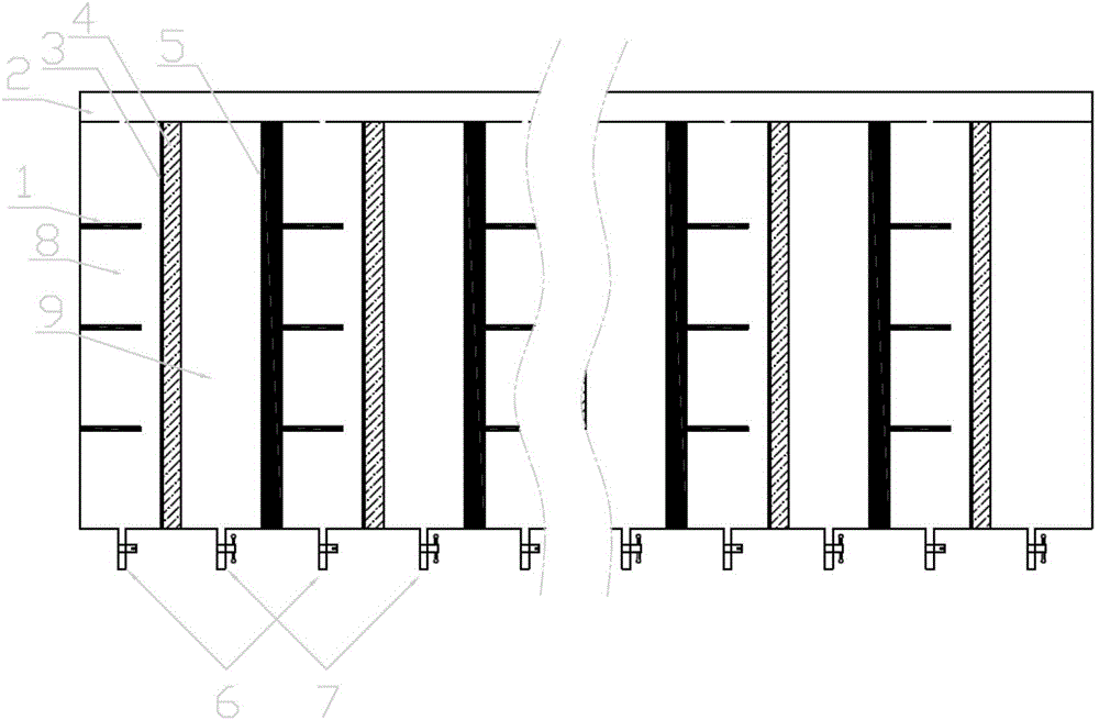
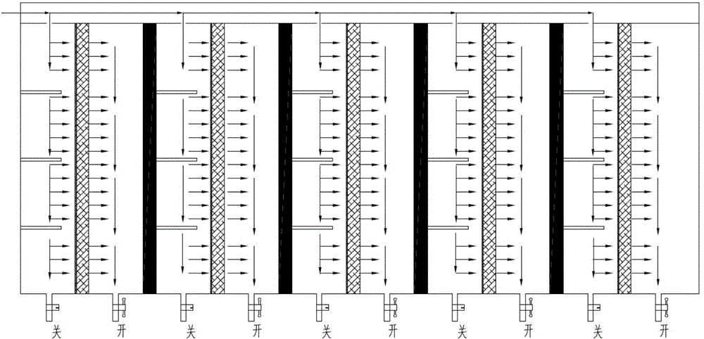
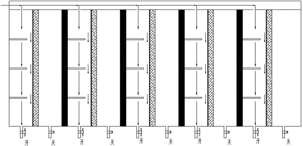
[0039] Such as figure 1 As shown, an oil-water separation device for treating oily sewage according to the present invention includes a plate-and-frame membrane module separator formed by staggered arrangement of separation plates and separators 5, wherein the odd-numbered plates are the separation plates, and the even-numbered plates are the separators 5. Form a plurality of separation units, adopt the vertical membrane module method, the separation plate and the partition plate 5 are placed upright, the upper part of the separator is connected to the liquid inlet channel 2, and the interior is separated by the separation plate and the partition plate 5 Divided into a separation chamber 8 and a filtrate chamber 9, the partition 5 is an I-shaped partition, the upper end of which is located in the separation chamber is provided with a round hole for liquid to enter, and the round hole communicates with the liquid inlet channel 2. The lower ends of the separation chamber 8 and t...
Embodiment 2
[0044] Such as figure 1 As shown, an oil-water separation device for treating oily sewage according to the present invention includes a plate-and-frame membrane module separator formed by staggered arrangement of separation plates and separators 5, wherein the odd-numbered plates are the separation plates, and the even-numbered plates are the separators 5. Form a plurality of separation units, adopt the vertical membrane module method, the separation plate and the partition plate 5 are placed upright, the upper part of the separator is connected to the liquid inlet channel 2, and the interior is separated by the separation plate and the partition plate 5 Divided into a separation chamber 8 and a filtrate chamber 9, the partition 5 is an I-shaped partition, the upper end of which is located in the separation chamber is provided with a round hole for liquid to enter, and the round hole communicates with the liquid inlet channel 2. The lower ends of the separation chamber 8 and t...
Embodiment 3
[0049] Such as figure 1 As shown, an oil-water separation device for treating oily sewage according to the present invention includes a plate-and-frame membrane module separator formed by staggered arrangement of separation plates and separators 5, and the plate-and-frame membrane module is separated by 1 square meter 10 layers of plates are superimposed, in which the odd numbered plates are separation plates, and the even numbered plates are separators 5, forming multiple separation units. The size of the separator is 1.5 meters × 1.5 meters × 8 meters. Both the plate and the partition 5 are placed upright, the upper part of the separator is connected with the liquid inlet channel 2, and the interior is divided into a separation chamber 8 and a filtrate chamber 9 by the separation plate and the partition 5, and the partition 5 is an I-shaped The upper end of the part located in the separation chamber is provided with a circular hole for liquid to enter, and the circular hole ...
PUM
| Property | Measurement | Unit |
|---|---|---|
| thickness | aaaaa | aaaaa |
| diameter | aaaaa | aaaaa |
| thickness | aaaaa | aaaaa |
Abstract
Description
Claims
Application Information
 - R&D
- Intellectual Property
- Life Sciences
- Materials
- Tech Scout
- Unparalleled Data Quality
- Higher Quality Content
- 60% Fewer Hallucinations
Browse by: Latest US Patents, China's latest patents, Technical Efficacy Thesaurus, Application Domain, Technology Topic, Popular Technical Reports.
© 2025 PatSnap. All rights reserved.Legal|Privacy policy|Modern Slavery Act Transparency Statement|Sitemap|About US| Contact US: help@patsnap.com


