
A magnetic levitation hydraulic centrifugal device

A centrifugal device and magnetic levitation technology, applied in the mechanical field, can solve the problems of complex control system, strong magnetic field, heavy cooling system, etc., and achieve the effect of simplifying the control system, stable performance, and reducing operation and maintenance costs

Inactive Publication Date: 2019-06-28
朱江
View PDF4 Cites 0 Cited by
  • Summary
  • Abstract
  • Description
  • Claims
  • Application Information

AI Technical Summary

Problems solved by technology

[0053] 2) The levitation height of the conventional magnetic levitation technology is low
[0054] 3) Due to the eddy current effect of superconducting magnetic levitation technology, the energy consumption of levitation is greater than that of conventional magnetic levitation technology, the cooling system is heavy, the cost is relatively high, the whole system is also complicated, and the strong magnetic field has an impact on the human body and the environment
[0066] 1. The traditional mechanical centrifugal technology relies on the motor to provide kinetic energy, which consumes a lot of energy;
[0067] 2. The current magnetic levitation centrifugal technology is mainly used in the field of refrigeration compressors, and the main core technology is the use of magnetic levitation bearings, but it is basically blank in the field of centrifugal separation, which is widely used, which cannot but be said to be a great pity;
[0068] 3. The existing magnetic suspension bearing mainly uses electromagnetic energy, which consumes a lot of energy and the control system is relatively complicated

Method used


Image

  • A magnetic levitation hydraulic centrifugal device
  • A magnetic levitation hydraulic centrifugal device
  • A magnetic levitation hydraulic centrifugal device

Examples


Embodiment Construction

[0095] The present invention is described in further detail below in conjunction with accompanying drawing:

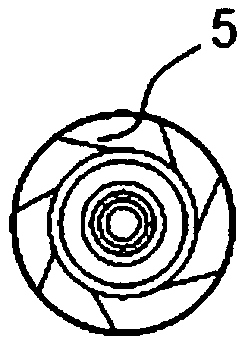
[0096] see figure 1 , 2 3. The maglev hydraulic centrifuge tank is a large cylindrical tank with an inverted conical lower part and a small valve outlet at the bottom. 2-3 or more rotating permanent magnet circles are welded on the outside of the cone, and the magnetic pole direction is N-S from inside to outside, or S-N. In addition, there are 2 to 3 or more fixed permanent magnet coils whose diameter is slightly larger than that of the magnetic levitation hydraulic centrifuge tank, and the magnetic pole direction is just in line with the magnetic pole direction of the rotating permanent magnet coil of the magnetic levitation hydraulic centrifuge tank. on the contrary. Such as figure 2 shown. Like this, when the magnetic levitation hydraulic centrifuge tank is placed on the support frame, because the external magnetic poles of its permanent magnet ring are ident...


PUM


Abstract

The invention discloses a magnetic levitation hydraulic centrifugation device which comprises a tank body, an inner cylinder E and a support rack, wherein the tank body consists of a lower inverted conical body D and an upper cylindrical tank body C; a small-size valve outlet V is formed in the bottom of the inverted conical body D; tank cone permanent magnetic rings A are fixed outside the inverted conical body; the support rack is arranged below the magnetic levitation hydraulic centrifugation device; rack cone permanent magnetic rings A' are fixed on the support rack; the magnetic pole directions of the rack cone permanent magnetic rings A' are just opposite to those of the tank cone permanent magnetic rings A; the tank cone permanent magnetic rings A and the rack cone permanent magnetic rings A' form permanent magnetic ring groups. The defect that a conventional permanent magnetic ring cannot be effectively controlled is overcome, the centrifugation separation purpose is achieved, at the same time, the advantages that a permanent magnet is simple in structure and stable in property are given full play, the problem that a conventional control unit is high in manufacturing and operation expense is effectively solved, the control system is simplified, and the operation maintenance cost and the energy consumption expense are greatly reduced.

Description

Technical field: [0001] The invention belongs to the field of machinery, and relates to a magnetic levitation hydraulic centrifugal device, in particular to a magnetic levitation hydraulic centrifugal device for separating substances of different densities contained in a liquid. Background technique: [0002] Chinese patent CN201320893256.0 discloses a magnetic levitation hydraulic centrifugal tank for the full resource utilization of seawater. The residual pressure of the pump outlet water is used as the direct power. On the premise of not increasing the power consumption, the potential energy poured into the seawater is converted into the tank The kinetic energy of body rotation drives the magnetic levitation hydraulic centrifuge tank to rotate around the central axis, thereby separating substances with different specific gravity in seawater, including separating heavy water and fresh water through the magnetic levitation hydraulic centrifuge tank, and separating uranium an...

Claims


Application Information

Patent Timeline
Patent Type & Authority Patents(China)
IPC IPC(8): C02F1/38C02F1/48
CPCC02F1/385C02F1/482C02F1/488C02F2201/48C02F2301/026
Inventor 朱江谢勇
Owner 朱江
Learn More