
A three-dimensional fluttering flapping wing drive mechanism

A driving mechanism, three-dimensional technology, applied in the directions of helicopters, motor vehicles, aircraft, etc., can solve the problems of low mechanical efficiency flapping aerodynamic efficiency, low mechanical efficiency and aerodynamic efficiency, difficult miniaturization or even miniaturization, etc., to increase transmission reliability. Performance and transmission efficiency, improved mechanical efficiency, easy miniaturization effect

Inactive Publication Date: 2017-04-26
NORTHWESTERN POLYTECHNICAL UNIV
View PDF11 Cites 0 Cited by
  • Summary
  • Abstract
  • Description
  • Claims
  • Application Information

AI Technical Summary

Problems solved by technology

[0004] China Patent Authorization Announcement No. CN102211666A, authorized announcement date October 12, 2011, the invention name is a kind of miniature flapping wing aircraft, the invention discloses a flapping wing driving mechanism and flapping wing using bevel gear transmission and crank-link mechanism. Wing aircraft, this design structure is relatively simple, but the disadvantage is that the mechanical efficiency and the aerodynamic efficiency of the flapping wings are low
Its disadvantages are that the composition is relatively complex, it is difficult to miniaturize, and its application on micro-flapping-wing aircraft is limited; in the flapping motion with high frequency, the alternating load is large, and the stability and reliability are poor
[0006] To sum up, the main problems of the existing flapping wing drive mechanism are that the structure is complex and heavy, it is difficult to miniaturize or even miniaturize, the mechanical efficiency and aerodynamic efficiency are low, and the stability and reliability are poor.

Method used


Image

  • A three-dimensional fluttering flapping wing drive mechanism
  • A three-dimensional fluttering flapping wing drive mechanism
  • A three-dimensional fluttering flapping wing drive mechanism

Examples


Embodiment

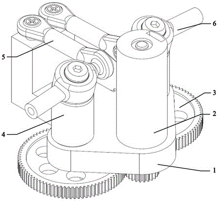
[0031] see Figure 1 ~ Figure 3 , This embodiment provides a flapping wing drive mechanism, including a frame 1, a motor 2, a reduction gear set 3, a linkage guide rod 4, a rocker arm 5, and a ball joint seat connecting rod 6.

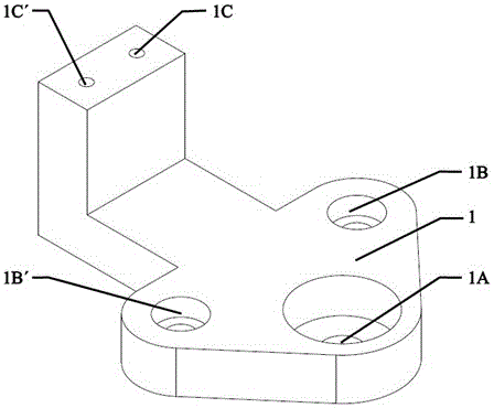
[0032] Rack 1, there is a drive gear shaft hole 1A at the bottom and a pair of driven gear shaft holes parallel to each other, namely the first driven gear shaft hole 1B and the second driven gear shaft hole 1B', and a pair of driven gear shaft holes on the top plane The screw holes are respectively the first screw hole 1C and the second screw hole 1C', which are used to securely connect the ball hinge;

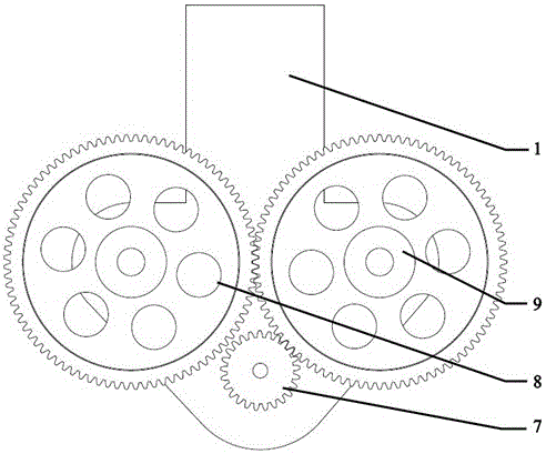
[0033] The motor 2 and the reduction gear group 3 are directly installed on the frame 1. The reduction gear group includes a driving gear 7 and two driven gears, which are respectively a first driven gear 8 and a second driven gear 9, and the first driven gear Gear 8 and the second driven gear 9 are symmetrically distributed on the frame 1, wherein t...


PUM


Abstract

The invention relates to a three-dimensional flapping flapping-wing drive mechanism which comprises a rack, a motor, a reduction gear unit, linkage guide rods, spherical hinged support connecting rods and rocker arms, wherein the motor and the reduction gear unit are directly mounted on the rack, the upper surfaces of the linkage guide rods are inclined planes and are hinged with the middles of the rocker arms; the top of the rack is fixedly connected with a spherical hinge; one ends of the rocker arms are also fixedly connected with a spherical hinge; two ends of the spherical hinged support connecting rods are fixedly connected with a spherical hinged support, wherein one ends of the spherical hinged support connecting rods are connected with the spherical hinge on the rack, and the other ends of the spherical hinged support connecting rods are connected with the spherical hinge on the rocker arm. The flapping-wing drive mechanism is simple in structure and light in weight, the rocker arm can realize symmetric three-dimensional flapping under the condition that the mechanism dimension is very small, so that the flapping-wing can produce strong pneumatic force, has the relatively good pneumatic efficiency, and can be relatively well applied to a flapping-wing aircraft to obtain a relatively good flight performance.

Description

technical field [0001] The invention relates to a flapping-wing driving mechanism, in particular to a three-dimensional flapping-wing driving mechanism. The mechanism can be used for miniature flapping wing aircraft. Background technique [0002] In recent years, with the rapid development of MEMS technology, micro air vehicle has gradually become a new research hotspot. At the micro scale, the flapping-wing flight method takes into account the high-speed cruise of micro-fixed-wing aircraft and the hovering ability of rotary-wing aircraft, so it has received increasing attention. Representative ones include the "Delfly" series developed by Delft University in the Netherlands and the "Microbat" jointly developed by AeroVrionment and the University of California. However, these flapping-wing aircraft still have a certain distance from practicality. [0003] In nature, flying animals often achieve efficient flight through three-dimensional complex flapping. A high-efficiency...

Claims


Application Information

Patent Timeline
Patent Type & Authority Patents(China)
IPC IPC(8): B64C33/02
Inventor 李洋王利光付鹏杨文青宋笔锋唐伟薛栋钟京洋李博扬郭汉青王进
Owner NORTHWESTERN POLYTECHNICAL UNIV
Learn More