
Manipulator separating and classifying device

A separation device, manipulator technology, applied in the direction of manipulator, program control manipulator, chuck, etc., can solve the problems of ineffective separation and classification, personnel injury accidents, easy failures, etc., to avoid scratches and safety accidents, and reduce human resources. Cost, the effect of ensuring the quality of castings

Inactive Publication Date: 2015-04-01
CRRC CHANGZHOU AUTO PARTS CO LTD
View PDF7 Cites 6 Cited by
  • Summary
  • Abstract
  • Description
  • Claims
  • Application Information

AI Technical Summary

Problems solved by technology

[0003] The existing separation and cutting devices all use manual hydraulic pliers. The machine is heavy and laborious to operate. It requires people to work in close contact with the casting. The pliers body is inserted into the separation part of the casting and the runner for separation. Due to the high temperature of the casting, the surface There are many edges and corners, so there are certain safety hazards, and it is prone to failure. After frequent maintenance and repairs, it is necessary to rely on manpower to carry and classify the castings after they are separated from the runners. It takes 5-6 people to complete this process. The amount is huge; because it is on the rolling chain belt, it is easy to cause scratches on the castings, or even work-related accidents. The emergence of the manipulator is to better complete the work tasks, improve work efficiency and work Safety is also the development trend in the field of production technology in the future, but ordinary manipulators are only a grabbing job and cannot be effectively separated and classified

Method used


Image

  • Manipulator separating and classifying device
  • Manipulator separating and classifying device
  • Manipulator separating and classifying device

Examples


Embodiment Construction

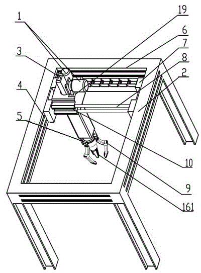
[0026] The invention discloses a device for separating and sorting manipulators, as shown in the attached figure 1 As shown, it includes a mobile seat frame 6, which can be fixed on both sides of the scale machine, and a first mobile actuator 10 is arranged on the mobile seat frame 6, and the first mobile actuator 10 includes guide rails The crossbeam 7 and the mobile guide rail 8 fixed between the guide rail crossbeams 7; The longitudinal movement guide rail 4 moves longitudinally.

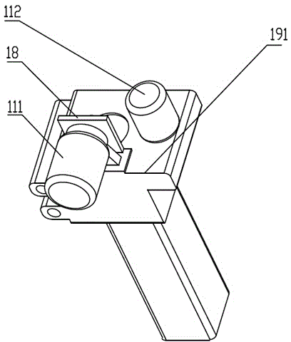
[0027] combined with figure 2 As shown, a main body device 19 is movably clamped on the moving guide rail 8 , and the main body device 19 includes a body 191 that moves laterally on the moving guide rail 8 . A driving motor unit 1 and a limit controller 18 are arranged above the body 191 , and the driving motor unit 1 includes a lifting motor 111 and a moving motor 112 . The bottom of the body 191 is provided with a mechanical arm 5 that can move axially relative to the body 191. The limit co...


PUM


Abstract

The invention discloses a manipulator separating and classifying device which comprises a moving seat frame. A driving motor group and a mechanical arm are arranged on the moving seat frame, the mechanical arm performs transverse, longitudinal and axial movement in the moving seat frame under the control of the driving motor group, a hydraulic power mechanism and a separating device arranged in the mechanical arm to perform reciprocating motion are arranged in the mechanical arm, and the separating device is connected with a mechanical clamp claw mechanism through a linkage mechanism. Under the effect of the hydraulic power mechanism, the separating device forwards extends out to separate parts to be separated. The mechanical clamp claw mechanism moves along with movement of the separating device. By means of the manipulator separating and classifying device, persons are prevented from being in contact with high-temperature parts with edges and corners in a close range mode, and the safety is improved. In addition, production efficiency is improved through automatic production, and labor cost is reduced.

Description

technical field [0001] The invention relates to a casting separation and sorting device, in particular to a manipulator separation and sorting device for casting separation and sorting. Background technique [0002] The manipulator separation technology is a mechanical device for dividing and classifying the cast parts of the production line, the riser sprue used in the process and other unrelated casting castings. Its advantages are automatic control, high precision and high efficiency, replacing manual work. It ensures safety, has a wide range of applications, and can effectively carry out continuous production. It is especially suitable for casting production lines with rapid production and high labor intensity. [0003] The existing separation and cutting devices all use manual hydraulic pliers. The machine is heavy and laborious to operate. It requires people to work in close contact with the casting. The pliers body is inserted into the separation part of the casting a...

Claims


Application Information

Patent Timeline
Patent Type & Authority Applications(China)
IPC IPC(8): B25J15/10B25J9/12B22D31/00
Inventor 张顺凯莫俊超张丹
Owner CRRC CHANGZHOU AUTO PARTS CO LTD
Learn More