
Stop device of bending machine

A technology of a material stopper and a bending machine, which is applied in the directions of a feeding device, a positioning device, a storage device, etc., can solve the problems that the stroke of the stroke rod cannot be guaranteed to be consistent, the folding accuracy cannot be guaranteed, and the operation is complicated, and the structure is simple. , easy to operate and ensure the effect of accuracy

Inactive Publication Date: 2015-04-01
马宁
View PDF5 Cites 0 Cited by
  • Summary
  • Abstract
  • Description
  • Claims
  • Application Information

AI Technical Summary

Problems solved by technology

[0002] A bending machine is a machine capable of bending thin plates. The stopper device is one of the important components in the bending machine. The existing stopper device is generally controlled manually, which is cumbersome to operate. Manually Control the stroke lever at one end, and then manually control the stroke lever at the other end, which cannot ensure that the strokes of the stroke levers at both ends are consistent, and ultimately cannot guarantee the accuracy of the hemming

Method used


Image

  • Stop device of bending machine
  • Stop device of bending machine

Examples


Embodiment Construction

[0012] The present invention is described in further detail now in conjunction with accompanying drawing. These drawings are all simplified schematic diagrams, which only illustrate the basic structure of the present invention in a schematic manner, so they only show the configurations related to the present invention.

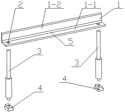
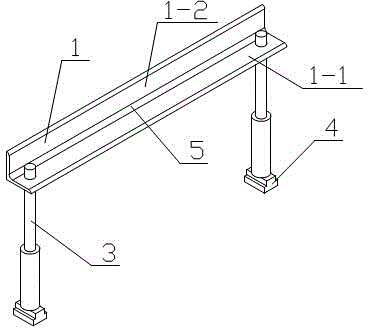
[0013] like figure 1 and figure 2 The material blocking device for the bending machine shown has a material blocking plate 1, the material blocking plate 1 includes a bottom plate 1-1 and a vertical plate 1-2 perpendicular to the bottom plate 1-1, and the left and right ends of the bottom plate 1-1 are respectively set There is a mounting hole 2, and each mounting hole 2 is fixedly connected with a stroke rod 3 by a fastening screw, and the bottom end of each stroke rod 3 is respectively equipped with a slide block 4, and the slide block 4 slides on the sliding track. A rounded corner 5 is provided at the connection between the base plate 1-1 and the vertic...


PUM


Abstract

The invention relates to the technical field of stop devices, particularly to a stop device of a bending machine. The stop device comprises a base plate and a vertical plate perpendicular to the base plate. Each of lateral ends of the base plate is provided with a mounting hole. Fastening screws are arranged in the mounting holes and allow the same to be fixedly connected with stroke rods. The bottoms of the stroke rods are provided with slide blocks respectively. The slide blocks slide on a slide rail. According to the arrangement, stokes of the stroke rods are electrically controlled and consistent.

Description

technical field [0001] The invention relates to the technical field of a material retaining device, in particular to a material retaining device for a bending machine. Background technique [0002] A bending machine is a machine capable of bending thin plates. The stopper device is one of the important components in the bending machine. The existing stopper device is generally controlled manually, which is cumbersome to operate. Manually Controlling the stroke lever at one end and then manually controlling the stroke lever at the other end cannot ensure that the strokes of the stroke levers at both ends are consistent, and ultimately the accuracy of the hemming cannot be guaranteed. Contents of the invention [0003] The technical problem to be solved by the present invention is: In order to solve the problems raised in the above-mentioned background technology, the present invention provides a material retaining device for a bending machine, which adopts electric control...

Claims


Application Information

Patent Timeline
Patent Type & Authority Applications(China)
IPC IPC(8): B21D43/00B21D19/00
CPCB21D43/26B21D19/00
Inventor 马宁
Owner 马宁
Learn More