Slew-rate-limited driver

A driver and slew rate limiting technology, applied in the field of microelectronics, can solve problems such as output voltage slew rate fluctuation, achieve the effect of easy implementation, reduce EMI and power feedthrough problems, and take into account the requirements of speed and slew rate

Active Publication Date: 2015-03-25
SHENZHEN STATE MICROELECTRONICS CO LTD
View PDF6 Cites 10 Cited by
  • Summary
  • Abstract
  • Description
  • Claims
  • Application Information

AI Technical Summary

Problems solved by technology

[0006] In view of this, the purpose of the present invention is to provide a slew-rate-limited driver to solve the problem that the driver in the prior art needs a large resistance and capacitance to achieve a large slew rate, and the output voltage slew rate fluctuates within a wide temperature range. question

Method used


Image

  • Slew-rate-limited driver
  • Slew-rate-limited driver
  • Slew-rate-limited driver

Examples


Embodiment Construction

[0019] In order to make the object, technical solution and advantages of the present invention clearer, the present invention will be further described in detail below in conjunction with the accompanying drawings and embodiments. It should be understood that the specific embodiments described here are only used to explain the present invention, not to limit the present invention.

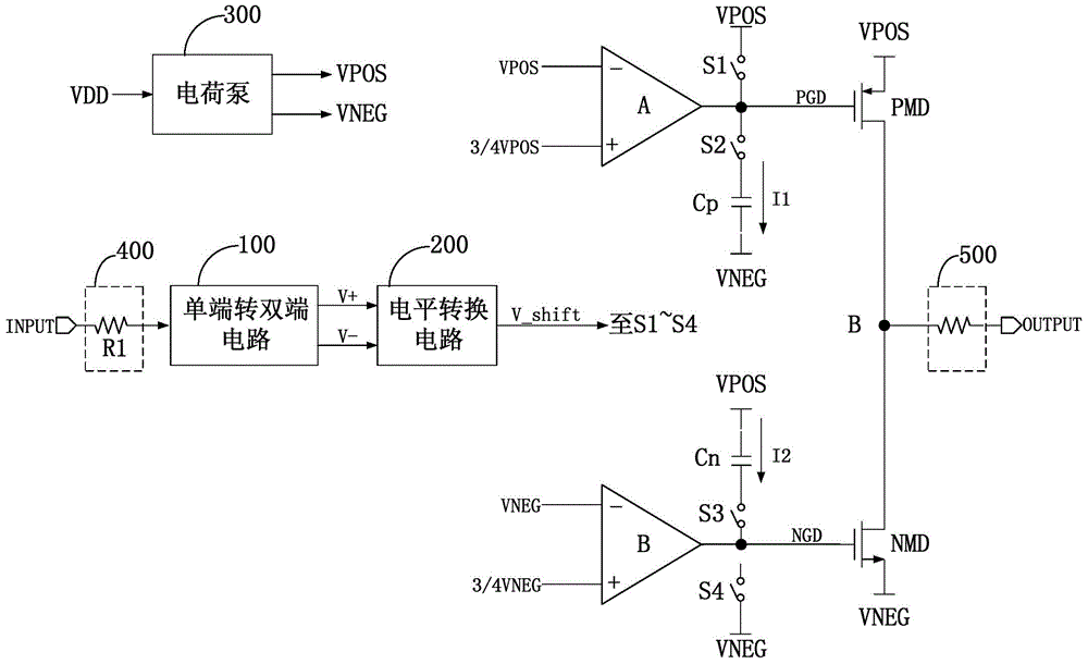
[0020] figure 2 It is a schematic diagram of the structure of the slew rate limiting driver provided by an embodiment of the present invention; for the convenience of description, only the parts related to this embodiment are shown, as shown in the figure:

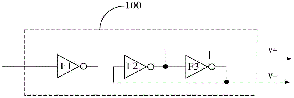
[0021] A slew rate limiting driver, comprising: a first comparator A, a second comparator B, a switch S1, a switch S2, a switch S3, a switch S4, a first drive transistor PMD and a capacitor Cp, a second drive transistor NMD and a capacitor Cn , a single-ended to double-ended circuit 100 and a level conversion circuit 200.

[0022] See the sp...


PUM


Abstract

The invention belongs to the field of micro-electronics, and particularly relates to a slew-rate-limited driver. Drive control is carried out on grid electrodes of a drive tube through two comparators, charging and discharging of a capacitor are carried out through a pull-up switch, a pull-down switch and a current source in a cooperative mode, the effect of controlling the output voltage slew rate is realized, and EMI and power source feed through problems can be effectively reduced. Meanwhile, the slew-rate-limited driver does not need a large resistor, and influence of the temperature excursion effect of the resistor on the output voltage slew rate is avoided. In addition, the slew-rate-limited driver is simple in circuit structure and easy to realize, output voltage in a wide temperature change range can still keep a stable slew rate, and the requirements for the speed and slew rate are also taken into account.

Description

technical field [0001] The invention belongs to the field of microelectronics, in particular to a slew rate limiting driver. Background technique [0002] The serial interface circuit has been widely used because of its early birth, simple and convenient use, and low cost, and it can be applied to large-scale long-distance transmission and other reasons. Especially in the field of industrial automation, a large number of devices use various serial interfaces. line interface circuit for connection. [0003] Theoretical analysis and experimental results show that the slower slew rate can effectively suppress the reflection caused by the impedance mismatch of the transmission line, reduce the influence of the connection line from the bus to the device on the signal, and simplify the connection of the device. Therefore, when designing the driver, the slew rate of the output signal should be slowed down as much as possible under the premise of ensuring the transmission rate. ...

Claims


Application Information

Patent Timeline
Patent Type & Authority Applications(China)
IPC IPC(8): H03K19/003
Inventor 吴庆轩黎炜杜明兰云鹏尚林林谷京儒
Owner SHENZHEN STATE MICROELECTRONICS CO LTD
Why Eureka
Try Eureka