High-voltage overhead line system grounding device
A grounding device, catenary technology
- Summary
- Abstract
- Description
- Claims
- Application Information
AI Technical Summary
Problems solved by technology
Method used
Image

Examples
Embodiment 1
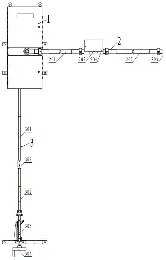
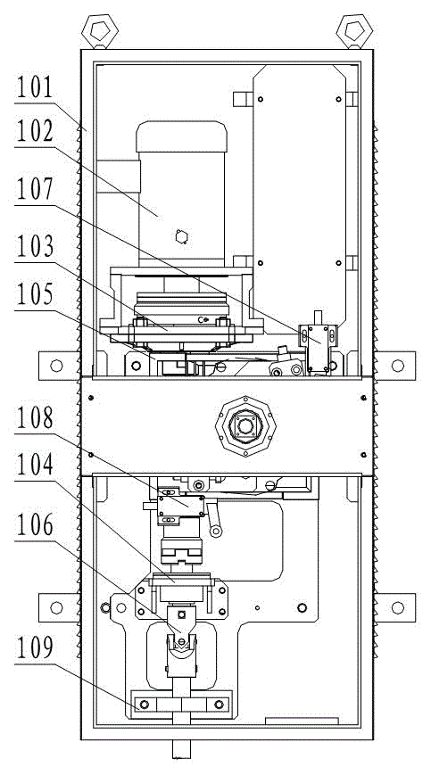
[0020] Such as figure 1 and figure 2 As shown, the high-voltage catenary grounding device includes a driving box assembly 1 and a rocker grounding rod assembly 2, wherein the driving box assembly 1 includes a box body 101, a driving motor 102, an upper clutch 103 and a reducer 105, and the driving motor 102. The upper clutch 103 and the speed reducer 105 are both arranged in the box body 101, the upper clutch 103 is connected with the output shaft of the drive motor 102 and the input shaft of the speed reducer 105, the rocker arm ground rod assembly 2 is connected with the side wall of the output shaft of the speed reducer 105 Connect vertically.
[0021] When this embodiment is applied, when it is necessary to realize the grounding of the catenary, the upper clutch 103 is engaged, the driving motor 102 acts on the upper clutch 103, and then acts on the reducer 105, and the reducer 105 drives the rocker arm grounding rod assembly 2 to contact The net contacts, and then real...
Embodiment 2
[0023] This embodiment makes the following further limitations on the basis of Embodiment 1: the rocker ground rod assembly 2 of this embodiment includes an upper insulating rod 201, a lower insulating rod 202, an elastic member 205, a grounding cable and a grounding knife 203, Wherein, the two ends of the elastic member 205 are respectively connected to one end of the upper insulating rod 201 and one end of the lower insulating rod 202, the other end of the upper insulating rod 201 opposite to the end of the elastic member 205 is connected to the output shaft of the reducer 105, and the lower insulating rod 202 The other end opposite to the end of the elastic member 205 is connected to the ground knife 203 , and the ground cable is connected to the ground knife 203 .
Embodiment 3
[0025] This embodiment makes the following further limitations on the basis of Embodiment 1 or Embodiment 2: the rocker ground rod assembly 2 of this embodiment also includes a limit switch 204, wherein the limit switch 204 is arranged on the upper insulating rod 201 and the connecting part of the lower insulating rod 202. The upper limit switch 107 and the lower limit switch 108 are also arranged in the box body 101 of the present embodiment, the upper limit switch 107 is arranged on the oblique upper side of the lower limit switch 108, and the rocker ground rod assembly 2 passes through the upper limit switch 107 and the lower limit switch 107. area between bit switches 108.
[0026] When this embodiment is applied, an electrical control system is used for control. The electrical control system includes an air switch, a contactor, an electromagnetic relay, a time relay, a transformer and a DC rectifier bridge. The driving motor 102, the limit switch 204, the upper limit Swi...
PUM
 Abstract
Description
Claims
Application Information
 - R&D
- Intellectual Property
- Life Sciences
- Materials
- Tech Scout
- Unparalleled Data Quality
- Higher Quality Content
- 60% Fewer Hallucinations
Browse by: Latest US Patents, China's latest patents, Technical Efficacy Thesaurus, Application Domain, Technology Topic, Popular Technical Reports.
© 2025 PatSnap. All rights reserved.Legal|Privacy policy|Modern Slavery Act Transparency Statement|Sitemap|About US| Contact US: help@patsnap.com