
Communication connector and terminal frame thereof

A terminal frame and connector technology, applied in the direction of connection, parts of connection devices, contact parts, etc., can solve problems such as unbalance, symmetry, affecting transmission efficiency, affecting conductor impedance, etc.

Active Publication Date: 2015-03-25
STARCONN ELECTRONICS SU ZHOU CO LTD
View PDF3 Cites 3 Cited by
  • Summary
  • Abstract
  • Description
  • Claims
  • Application Information

AI Technical Summary

Problems solved by technology

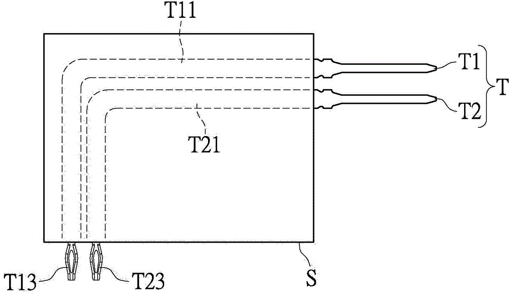
Generally speaking, the common dielectric coefficient of these dielectric shells S is about 3-4. Generally speaking, the dielectric shell S covers the differential terminal pair T or the internal conductor of the electrical connector, which can be used as a barrier to the outside world. For insulation purposes, although the dielectric shell S can provide good protection and insulation effects, but because the conductor is covered by the dielectric shell S, it affects the impedance of the conductor itself, which in turn affects the transmission efficiency. Such problems are in use The impact on the electrical connector that transmits the differential signal is relatively large, and the connector that uses the differential terminal pair T for transmission is most affected, because the differential terminal pair T must have a long path in the connector at this time. The other two terminals with a shorter path, so the two terminals in the differential terminal pair T are inherently unbalanced and symmetrically transmitted, and the two terminals of different lengths must not be affected by the dielectric shell S The same, so it highlights the difference in transmission between the two terminals. However, this has a key impact on the transmission of high-frequency differential signals that cannot be ignored but has not been resolved. For connectors with unequal terminal lengths, there is still room for improvement in the transmission frequency and efficiency of high-frequency differential signals

Method used


Image

  • Communication connector and terminal frame thereof
  • Communication connector and terminal frame thereof
  • Communication connector and terminal frame thereof

Examples


Embodiment Construction

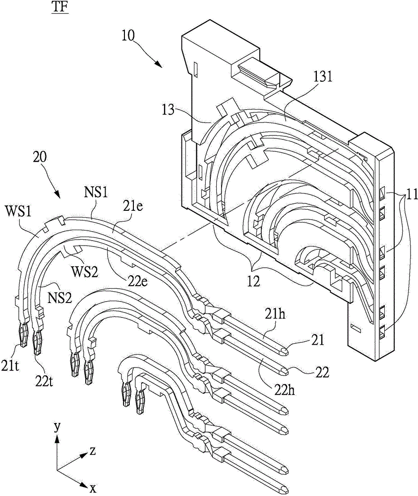
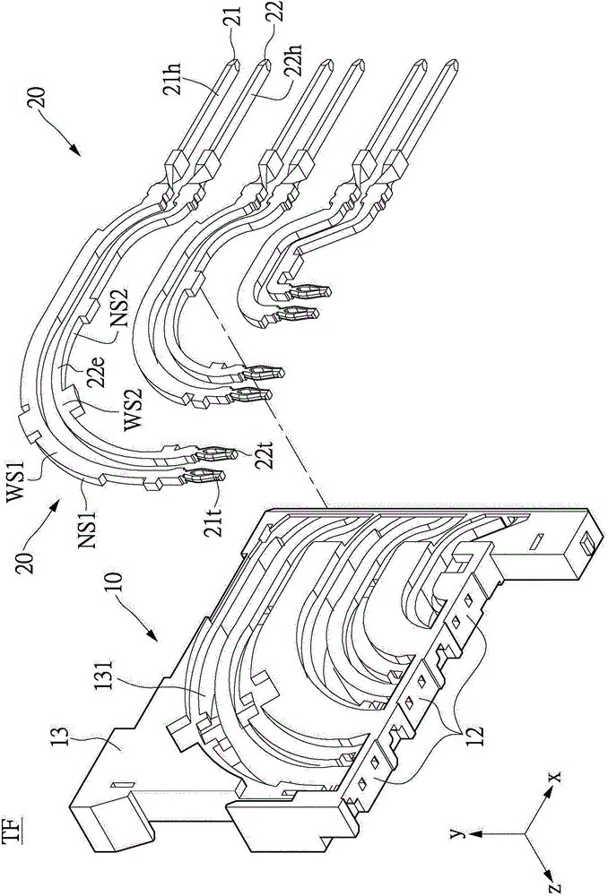
[0090] see Figure 2A , Figure 2B and Figure 2D As shown, it is a relevant exemplary schematic diagram of an embodiment of the terminal frame TF in the present invention. The terminal frame TF provided in the present invention includes: an insulating frame 10, and multiple pairs of terminal pairs 20 arranged in the insulating frame 10. Three pairs of terminal pairs 20 are shown in the figure as an example, but not limited thereto.

[0091] The insulating frame 10 can be an insulating plastic or any other insulating material, so its material is not limited, and the insulating frame 10 is the first medium (or called the first dielectric) that the terminal pair 20 can come into contact with. quality, the label is omitted), so it has a dielectric coefficient. Taking plastic as an example, its dielectric coefficient is mostly around 3 or 4. The insulating frame 10 also includes at least a head extension 11, a tail extension 12 and two side surfaces 13. The head extension 11 an...


PUM


Abstract

Provided are a communication connector and a terminal frame thereof. The terminal frame comprises an insulating frame and a plurality of pairs of terminal pairs in the insulating frame. The insulating frame is a first medium and at least comprises a side surface. The terminal pair comprises a first terminal and a second terminal. The first terminal comprises a first extending portion which extends along a first path in the insulating frame. The second terminal comprises a second extending portion which extends along a second path in the insulating frame. The first path is longer than the second path. The first extending portion contacts with a second medium, so that the first extending portion has first contact area relative to the contact second medium, and the second extending portion has second contact area relative to the contact second medium, and the first contact area is larger than the second contact area. Thus, transmission quality of the terminal pairs is improved.

Description

technical field [0001] The present invention relates to a communication connector and its terminal frame, in particular to a method involving changing or improving the communication transmission effect of high-frequency data of the communication connector by changing the composition of the dielectric material contacted by an electrical terminal. A communication connector and a terminal frame thereof. Background technique [0002] see figure 1 As shown, it is an example of a known connector or a communication connector, basically, a pair of differential terminals T is often used for electrical transmission. The first head end T1 of the differential terminal pair T extends from an outside of the dielectric housing S and enters the dielectric housing S, so that the dielectric housing S covers the first terminal intermediate lead T11 inside it. , and then the middle lead T11 of the first terminal will extend from the other outside of the dielectric shell S to the first tail en...

Claims


Application Information

Patent Timeline
Patent Type & Authority Applications(China)
IPC IPC(8): H01R13/46H01R13/40H01R13/02
CPCH01R13/6587H01R13/46H01R13/02H01R13/40
Inventor 包中南王孝银林钰雄
Owner STARCONN ELECTRONICS SU ZHOU CO LTD
Learn More