Automatic drawing frame for diode

A sliver and diode technology, applied in the field of machinery, can solve the problems of increased manufacturing cost of diodes, difficulty in manual handling of diodes, low work efficiency, etc., and achieve the effects of convenient production and processing, improved production and processing efficiency, and structural energy saving.

Inactive Publication Date: 2015-03-25
CHANGZHOU COLLEGE OF INFORMATION TECH
View PDF5 Cites 6 Cited by
  • Summary
  • Abstract
  • Description
  • Claims
  • Application Information

AI Technical Summary

Problems solved by technology

The tray transfer of these diodes is currently done manually, with a very heavy workload and low work efficiency, which greatly increases the manufacturing cost of the diodes.
Based on the above reasons, some diode manufacturers have considered relocating their enterprises to provinces or cities with lower labor wages. Although it can alleviate the pressure on costs, the efficiency is still very low.
[0003] There have also been technicians who tried to use a vacuum suction cup to transfer the entire diode diode at one time. Because the diode pins are soft and easy to bend, there are 1,500 diodes inserted in a tray, and it is impossible for them all to be parallel to each other. Erection, there is a considerable amount of lodging during the transfer process, and the lodging diode is more difficult to handle manually, and the actual operation is less efficient and unfeasible

Method used


Image

  • Automatic drawing frame for diode
  • Automatic drawing frame for diode
  • Automatic drawing frame for diode

Examples


Embodiment 1)

[0072] See figure 1 , The diode automatic sliver machine of the present invention includes a frame 1, a transfer device 2 and a clamping device 3. The transfer device 2 is arranged on the frame 1 .

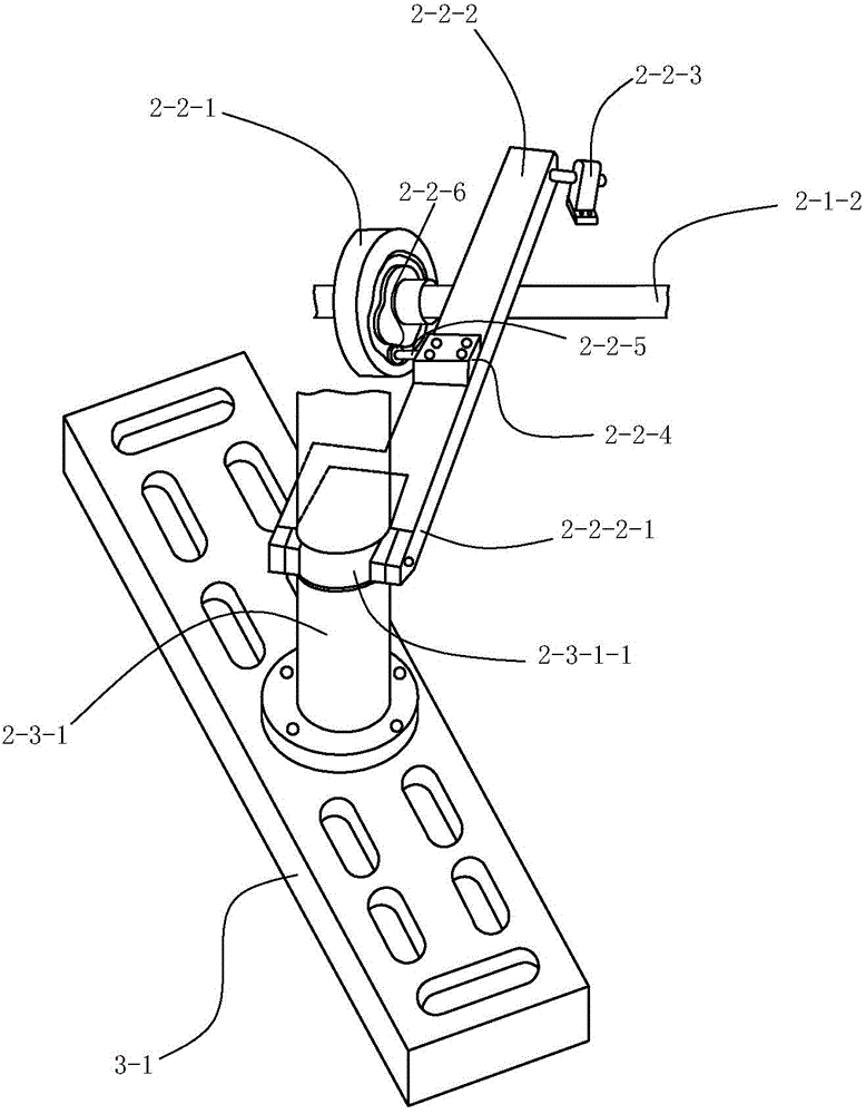
[0073] See figure 2 , The transfer device 2 includes a driving mechanism 2-1, a lifting mechanism 2-2 and a turning mechanism 2-3.

[0074] See figure 1 with figure 2 , the drive mechanism 2-1 includes a motor 2-1-1 and a drive shaft 2-1-2. The motor 2-1-1 is fixedly arranged on the frame 1, and the motor 2-1-1 is arranged horizontally backward by its motor shaft. The drive shaft 2-1-2 is rotatably arranged on the frame, and is connected with the motor shaft transmission of the motor 2-1-1, and the drive shaft 2-1-2 is driven by the motor 2-1-1 to rotate.

[0075] See figure 2 , image 3 with Figure 7, the lifting mechanism 2-2 includes a lifting cam 2-2-1, an adjusting arm 2-2-2, an adjusting arm mounting seat 2-2-3, an adjusting arm guide seat 2-2-4, and an adjustin...


PUM


Abstract

The invention discloses an automatic drawing frame for a diode. The automatic drawing frame is characterized by comprising a rack, a transfer device and a clamping device. The transfer device is arranged on the rack and comprises a driving mechanism, a lifting mechanism and a rotating mechanism. The lifting mechanism and the rotating mechanism are driven by the driving mechanism to move. The rotating mechanism is provided with a rotating shaft and a rotating shaft support, and the rotating shaft conducts intermittent reciprocating motion in the intermittent 180-degree rotation direction and intermittent straight reciprocating motion in the axial direction of the rotating shaft. The clamping device comprises a connecting plate, grabbing components and positioning components, the connecting plate is fixedly arranged at the lower end of the rotating shaft, the left grabbing component and the right grabbing component have the same structure and are arranged at the left end and the right end of the connecting plate by taking the axis of the rotating shaft as a symmetry axis in a bilateral symmetry mode, the left positioning component and the right positioning component have the same structure and are arranged on the left side and the right side of the rack by taking the axis of the rotating shaft as the symmetry axis in a bilateral symmetry mode, and the positioning components are used for positioning the grabbing components and controlling grabbing and loosening movement of the grabbing components.

Description

technical field [0001] The technical field of the invention relates to an automatic sliver machine for quickly transferring diodes from a template of the previous process to a template of the next process on a production line. Background technique [0002] During the production and processing of diodes, there are several processes that must change the template. For example, hundreds of diodes need to be inserted into the plastic tray (template) during pickling. After pickling, it is transferred to the gluing and drying process. in a metal tray (formwork). The pallet transfer work of these diodes is currently done manually, with a very heavy workload and low work efficiency, which greatly increases the manufacturing cost of the diodes. Based on the above reasons, some diode manufacturers have considered relocating their enterprises to provinces or cities with lower labor wages. Although the cost pressure can be alleviated, the efficiency is still very low. [0003] There ha...

Claims


Application Information

Patent Timeline
IPC IPC(8): H01L21/677H01L21/683H01L21/329
CPCH01L21/67703H01L21/68H01L21/687
Inventor 巢雨苍巢惟忐
Owner CHANGZHOU COLLEGE OF INFORMATION TECH
Why Eureka
Try Eureka