Ultrasonic wire bonding wire-lost detection device and method

A wire-bonding and wire-detection technology, applied in measuring devices, measuring electricity, measuring electrical variables, etc., can solve the problems of slow detection, waste of manpower, untimely failure, etc., achieve concentrated distribution of characteristic values, and reduce false alarms rate, detection accuracy

Inactive Publication Date: 2018-05-08
HARBIN INST OF TECH SHENZHEN GRADUATE SCHOOL
View PDF5 Cites 0 Cited by
  • Summary
  • Abstract
  • Description
  • Claims
  • Application Information

AI Technical Summary

Problems solved by technology

This kind of off-line detection cannot timely feed back the fault information related to the key joint system
Use a high-power microscope to observe whether the lead wire is broken with the naked eye. The problem is that a large amount of manpower is required to check the working process, and only a fixed time interval can be used for random inspection. Failures are not found in time, and a lot of manpower is wasted, resulting in high costs.
[0003]The method of measuring the feeding amount of the lead wire through the rotary encoder has the problem that the feed amount of the lead wire changes very little, so it is not timely to find the wire breakage, and generally it takes The broken wire can only be detected after bonding about 40 times after the wire is broken, and the detection speed is slow
The problem with the method of batch identification of solder joints through computer vision is that firstly, a certain number of bonding needs to be met before unified detection, and the fault is not found in time. Secondly, there are many reasons for the failure of the bonding point, and it is not accurate to distinguish whether the cause of the fault is lost or not.

Method used


Image

  • Ultrasonic wire bonding wire-lost detection device and method
  • Ultrasonic wire bonding wire-lost detection device and method
  • Ultrasonic wire bonding wire-lost detection device and method

Examples


Embodiment Construction

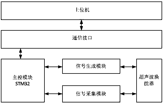
[0025] refer to figure 1 Shown: device of the present invention is mainly by above figure 1 Composed of 6 modules shown in : The detected signal is the impedance signal during the ultrasonic wire bonding process. Therefore, the above hardware structure is required to collect the impedance signal in real time during the working process. The functions completed by each module are as follows:

[0026] 1. Host computer: human-computer interaction interface, the operator can set the bonding parameters and disconnection detection parameters.

[0027] 2. Communication interface: realize the real-time data transmission between the lower computer and the upper computer, and transmit the alarm signal to the upper computer in time when a disconnection fault is detected.

[0028] 3. Main control module: The core chip is STM32, which realizes the decoding of the upper computer, the generation instruction of the driving signal, the processing of the collected signal and the realization o...


PUM


Abstract

The invention discloses an ultrasonic lead bonding line loss detection device which comprises an upper computer for an operator to set a bonding parameter and a loss detection parameter, a communication interface for achieving real-time data transmission with the upper computer and timely transmitting an alarm signal to the upper computer when detecting a line loss fault, a master control module (STW32) connected with the communication interface and used for achieving a method including the steps of generating a decoding and driving signal instrument of the upper computer, processing acquisition signal and judging line loss detection, a signal generating module, a signal acquisition module and an ultrasonic transducer connected with the signal generating module and the signal acquisition module, wherein the signal generating module and the signal acquisition module are connected with the master control module (STW32). By means of an ultrasonic lead bonding line loss detection method, an impedance signal in the ultrasonic lead bonding process is detected, the detection speed is higher than the speed in an existing detection method, the real-time detection effect can be achieved, and normal bonding work efficiency is not influenced.

Description

technical field [0001] The invention relates to microelectronic packaging quality detection technology, in particular to an ultrasonic wire bonding quality loss detection device and detection method. Background technique [0002] Ultrasonic wire bonding is one of the most important technologies in the interconnection of IC chips; it provides the interconnection of pins between chips and substrates; it refers to the ultrasonic vibration and bonding tools generated by piezoelectric transducers in a normal temperature environment Under the action of pressure, the wire (gold or aluminum wire) is bonded to the bottom pad of the chip, thereby connecting the chip and the circuit of the substrate together. The quality of the bonding point will directly affect the performance of the IC chip, and a small bonding point failure may cause the failure of the entire IC chip. During the ultrasonic wire bonding process, the detection of wire breakage due to excessive wire pulling, wire clip...

Claims


Application Information

Patent Timeline
Patent Type & Authority Patents(China)
IPC IPC(8): G01R31/02
Inventor 隆志力楼云江袁文郑元勋
Owner HARBIN INST OF TECH SHENZHEN GRADUATE SCHOOL
Why Eureka
Try Eureka