
Air cooling equipment for machining engine connecting rod

A technology for engine connecting rods and cooling equipment, which is applied to lighting and heating equipment, household refrigeration devices, household appliances, etc., can solve the problems of high connecting rods, and achieve the effects of convenient manufacture, lower temperature, and simple and novel structure

Inactive Publication Date: 2015-03-25
CHONGQING PENGSHI TECH DEV
View PDF0 Cites 3 Cited by
  • Summary
  • Abstract
  • Description
  • Claims
  • Application Information

AI Technical Summary

Problems solved by technology

In the existing structure, there are relatively high problems after the connecting rod is processed, and the processed connecting rod needs to be used in the next process in time. Therefore, the processed connecting rod needs to be cooled faster

Method used


Image

  • Air cooling equipment for machining engine connecting rod
  • Air cooling equipment for machining engine connecting rod

Examples


Embodiment Construction

[0013] The present invention will be further described below in conjunction with the embodiments and accompanying drawings.

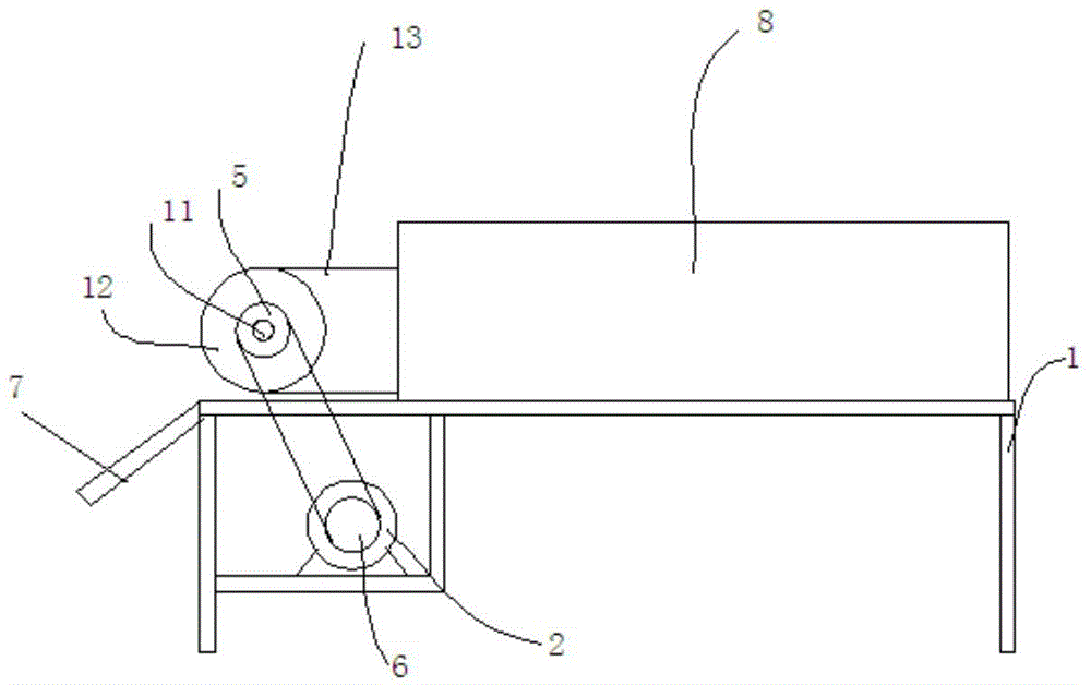
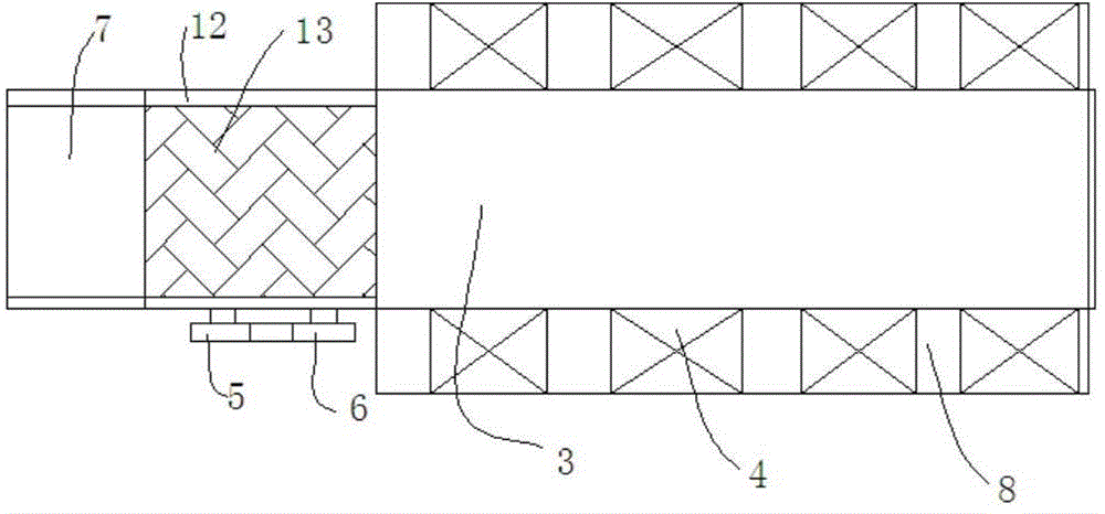
[0014] Such as figure 1 and figure 2 The shown air-cooled cooling equipment for engine connecting rod processing includes a support frame 1, on which a chain conveying mechanism 1 is installed, and the chain conveying mechanism 1 is connected to the output shaft of the motor 2, and the motor 2 is fixed on the On the support frame 1, a casing 3 is covered above the chain conveying mechanism 1, and both sides of the casing 3 are provided with a cooling air passage 8 communicating with the casing 3, and a cooling air passage 8 is provided in the cooling air passage 8. Cooling fan 4.

[0015] See figure 2 : the chain conveying mechanism 1 includes two drive shafts 11 installed on the support frame 1, the two ends of the drive shaft 11 are fixed to the conveying sprocket 12, and a chain conveyor belt 13 is installed on the conveying sprocket 12, A driv...


PUM


Abstract

The invention discloses air cooling equipment for machining an engine connecting rod. The air cooling equipment comprises a supporting frame, a chain conveying mechanism is installed on the supporting frame and connected with an output shaft of a motor, and the motor is fixed to the supporting frame. An outer shell is arranged above the chain conveying mechanism in a covering mode. Cooling air channels are formed in the upper portion of the outer shell, cooling fans are installed above the outer shell, and the lower portions of the cooling fans are located inside the cooling air channels. By the adoption of the structure, the temperature of the connecting rod is high after heating, rolling, forming, punching and edge trimming are performed on the connecting rod on a production line, and at the moment, the connecting rod high in temperature enters the outer shell under driving of the chain conveying mechanism; because the fans installed on the outer shell are in a working state, cold air enters the cooling air channels and cools the connecting rod.

Description

technical field [0001] The invention belongs to the technical field of processing engine connecting rods, and in particular relates to air-cooled cooling equipment for processing engine connecting rods. Background technique [0002] In reciprocating piston power machines and compressors, connecting rods are used to connect the pistons to the crank. The connecting rod is mostly steel, and the cross-section of the main part is mostly circular or I-shaped. There are holes at both ends, and bronze bushings or needle bearings are installed in the holes, which are used for loading shaft pins to form hinges. The connecting rod is an important part in engines such as automobiles and ships. It connects the piston and the crankshaft. Its function is to convert the reciprocating motion of the piston into the rotational motion of the crankshaft, and transfer the force acting on the piston to the crankshaft to output power. When the connecting rod is working, in addition to bearing the ...

Claims


Application Information

Patent Timeline
Patent Type & Authority Applications(China)
IPC IPC(8): F25D1/00
CPCF25D1/00
Inventor 彭其军
Owner CHONGQING PENGSHI TECH DEV
Learn More