
Automatic lifting monitoring camera device with automatic coiling function

A monitoring camera, automatic wire winding technology, applied in the direction of supporting machines, mechanical equipment, machines/stands, etc., can solve the problems of cluttered cables, obstructing the lifting of light panels, and falling objects from high altitudes, saving processing time, preventing mutual The effect of winding and easy finishing

Inactive Publication Date: 2015-03-25
TIANJIN CHUANSHI TECH
View PDF3 Cites 8 Cited by
  • Summary
  • Abstract
  • Description
  • Claims
  • Application Information

AI Technical Summary

Problems solved by technology

However, because the lamp panel needs to rise and fall frequently, the monitoring camera will hinder the lifting of the lamp panel, so a set of equipment is required to be attached to the lifting high pole light, and the monitoring camera can be lifted freely to facilitate equipment installation and height adjustment
[0003] In addition, since the monitoring camera on the camera platform is connected with a power supply cable and a control cable, the cable hangs down to the signal cable storage box through the groove, and the cable of the monitoring camera will also be continuously reduced during the rising of the camera platform. As the camera platform descends, the number of cables hanging from the surveillance camera will continue to increase, resulting in the generation of redundant cables, which are messy and difficult to organize
If the cables are arranged manually, the danger of falling objects will easily occur during the ascent process, so a solution is urgently needed to improve the operation convenience and safety of the lifting system

Method used


Image

  • Automatic lifting monitoring camera device with automatic coiling function
  • Automatic lifting monitoring camera device with automatic coiling function
  • Automatic lifting monitoring camera device with automatic coiling function

Examples


Embodiment Construction

[0027] Embodiments of the present invention will be described in further detail below in conjunction with the accompanying drawings.

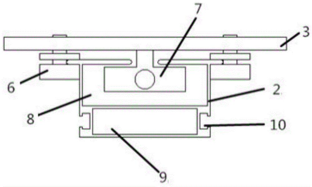
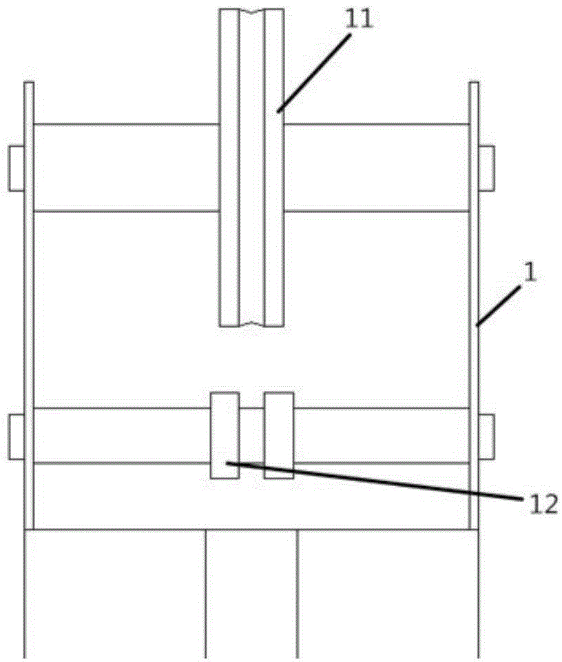
[0028] An automatic lifting monitoring camera device with automatic winding function, such as figure 1 As shown, it includes a lifting track 2, a camera platform 3, a pulley block 1, a motor transmission mechanism 4, and an automatic winding mechanism 5. The lifting track is vertically fixed on the surface of the pole body of the high pole lamp by hoops or rivets, the camera platform is slidably installed on the lifting track, the pulley block is installed on the top of the lifting track, and the motor The transmission mechanism is installed under the lifting track. The upper end of the camera platform is connected with the load-bearing wire rope. The other end of the load-bearing wire rope is connected with the motor transmission mechanism through the pulley block. The camera platform of the camera can complete the descending operation of the...


PUM


Abstract

The invention relates to an automatic lifting monitoring camera device with an automatic coiling function. The automatic lifting monitoring camera device is technically characterized by comprising a lifting track, a camera platform, a pulley block, a motor transmission mechanism and an automatic coiling mechanism, wherein the lifting track is fixedly installed on the surface of a rod body of a high-pole lamp; the camera platform is glidingly mounted on the lifting track; the pulley block is mounted at the top of the lifting track; the motor transmission mechanism is mounted below the lifting track; the motor transmission mechanism carries out lifting operation by pulling the camera platform through a loading steel wire rope; a monitoring camera is mounted on the camera platform; the automatic coiling mechanism and the motor transmission mechanism are connected with each other to coil a wire cable of the monitoring camera. The automatic lifting monitoring camera device with the automatic coiling function not only provides convenient conditions for the mounting and construction of the monitoring camera, but also regularly coils up the wire cable of the monitoring camera, so as to prevent the wire cable from damage caused by involvement, provides convenience for cable arrangement, improves the normal operation of the monitoring camera, saves the space, and reduces the construction cost and maintenance cost.

Description

technical field [0001] The invention belongs to the technical field of video monitoring, in particular to an automatic lifting monitoring camera device with an automatic winding function. Background technique [0002] In open places such as docks, yards, and squares, high pole lights are generally used as night lighting equipment. These high pole lights need to be frequently lifted and lowered for daily maintenance. Since the above-mentioned places also need to be monitored, the surveillance camera needs a certain height to monitor the entire environment. Therefore, the corresponding height can be obtained by installing the surveillance camera on the high pole light, which also saves installation costs and reduces installation difficulty. . However, because the lamp panel needs to rise and fall frequently, the monitoring camera will hinder the lifting of the lamp panel, so a set of equipment is required to be attached to the lifting high pole light, and the monitoring camer...

Claims


Application Information

Patent Timeline
IPC IPC(8): F16M13/02F16M11/04F16M11/18
Inventor 张宝寅任子江杜贺
Owner TIANJIN CHUANSHI TECH
Learn More