Variable-section self-locking leakage prevention device for large opening of internal-pressure vessel

A technology of internal pressure vessel and variable cross-section, which is applied in the field of leakage prevention, and can solve problems such as the inability to ensure the circumferential uniformity of flange edge compression, the difficulty of sealing the large opening end face of the internal pressure vessel, and the impact of bolts on the sealing effect, etc., to achieve structural Compact, easy to manufacture and install, good fit effect

Active Publication Date: 2015-03-25
中国船舶重工集团公司第七〇二研究所
View PDF6 Cites 0 Cited by
  • Summary
  • Abstract
  • Description
  • Claims
  • Application Information

AI Technical Summary

Problems solved by technology

[0002] There have always been many technical difficulties in the sealing of the large opening end face of the internal pressure vessel
The biggest disadvantage of this method is: the sealing performance will gradually decrease with the increase of the internal pressure of the container, and it is easy to leak under high pressure; and the fit of the sealing surface is very critical, and the uneven pre-tightening degree of the bolts will affect the sealing effect, so the pressure When it is low, all the bolts need to be pre-tightened, but even if all the bolts are installed, the circumferential uniformity of the compression of the flange edge cannot be guaranteed, so local leakage cannot always be avoided

Method used


Image

  • Variable-section self-locking leakage prevention device for large opening of internal-pressure vessel
  • Variable-section self-locking leakage prevention device for large opening of internal-pressure vessel
  • Variable-section self-locking leakage prevention device for large opening of internal-pressure vessel

Examples


Embodiment Construction

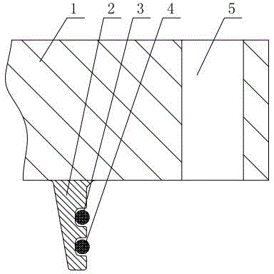
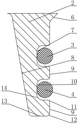
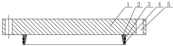
[0023] The specific implementation manner of the present invention will be described below in conjunction with the accompanying drawings.

[0024] Such as figure 1 , figure 2 , image 3 , Figure 4 and Figure 5 As shown, the variable-section self-locking anti-leakage device of the large opening of the internal pressure vessel of the present embodiment includes a flange flat cover 1, and a variable-section sealing ring 2 extends from the bottom of the flange flat cover 1, and the variable-section sealing ring 2 is Axisymmetric short cylindrical structure, the radial wall thickness of the variable cross-section sealing ring 2 linearly decreases from the root to the end; one end of the variable cross-section sealing ring 2 forms the internal pressure acting surface 8 of the container, and the other end forms the outer longitudinal sealing surface 9, which is located at the variable cross-section The outer longitudinal sealing surface 9 at the root of the cross-section seali...


PUM


Abstract

A variable-section self-locking leakage prevention device for a large opening of an internal-pressure vessel includes a flange flat cover. The bottom of the flange flat cover extends to form a variable-section seal ring which is of an axisymmetric short cylinder structure. The radial wall thickness of the variable-section seal ring decreases progressively from the root to the end of the variable-section seal ring. One end of the variable-section seal ring forms an internal-pressure acting surface of the vessel, and the other end of the variable-section seal ring forms an outer-side longitudinal sealing surface. The outer-side longitudinal sealing surface located at the root of the variable-section seal ring is provided with an outer-side reinforcing surface. A first groove and a second groove are formed in the position close to the lower end of the outer-side longitudinal sealing surface in a spaced mode. An outer-side chamfer angle is arranged at the bottom of the outer-side longitudinal sealing surface and located at the bottom surface of the variable-section seal ring. An open trunk bulkhead is formed in the inner wall face of an opening flange, and the outer-side longitudinal sealing surface of the variable-section seal ring abuts against the inner surface of the open trunk bulkhead. Because the radial thickness of the seal ring decreases progressively from the root to the end, the radial deformation of the end structure can be increased; in addition, the higher the internal pressure of the vessel is, the tighter the outer-side longitudinal sealing surface is attached, and therefore leakage is prevented.

Description

technical field [0001] The invention relates to the technical field of anti-leakage technology for large openings of internal pressure vessels, in particular to a variable-section self-locking anti-leakage device for large openings of internal pressure vessels. Background technique [0002] There have always been many technical difficulties in sealing the end face of the large opening of the internal pressure vessel. In the prior art, the commonly used flange sealing method is forced sealing, that is, the pre-tightening force is applied through the bolts, so that the flange surface and the sealing ring are pre-compressed and deformed before being subjected to internal pressure, and the pre-tightening force gradually increases during the pressurization process. Reduced, but there is still a compression margin on the sealing surface, so as to ensure that the medium in the container does not leak. The biggest disadvantage of this method is: the sealing performance will gradual...

Claims


Application Information

Patent Timeline
IPC IPC(8): F16J13/12
CPCF16J13/12
Inventor 邱昌贤黄进浩
Owner 中国船舶重工集团公司第七〇二研究所
Why Eureka
Try Eureka