
A reciprocating wind power generation system

A wind power generation system, reciprocating technology, applied in the direction of wind power generation, wind engine, wind motor combination, etc., can solve problems such as high difficulty, increase system complexity, high cost, etc., and achieve the effect of improving utilization rate

Inactive Publication Date: 2017-02-22
SHANDONG UNIV
View PDF5 Cites 0 Cited by
  • Summary
  • Abstract
  • Description
  • Claims
  • Application Information

AI Technical Summary

Problems solved by technology

[0003] At present, the horizontal axis wind turbine is the main structural form of wind energy utilization, but the entire wind turbine power generation system must be installed on a tower above the ground, resulting in high cost and difficulty in manufacturing, installation and maintenance. During the operation of the wind turbine , the entire wind turbine power generation system also needs to yaw against the wind according to the wind direction, which increases the complexity of the system and reduces the utilization rate of wind energy
In recent years, vertical axis wind turbines have also been developed and applied to a certain extent. Although the transmission system of vertical axis wind turbines can be installed on the ground, the blades still need to be installed on the tower, which increases the difficulty of system maintenance. The angle of attack of the vertical axis blade is fixed, which limits its application in low wind speed

Method used


Image

  • A reciprocating wind power generation system
  • A reciprocating wind power generation system
  • A reciprocating wind power generation system

Examples


Embodiment Construction

[0027] The present invention will be further described below in conjunction with the accompanying drawings and embodiments.

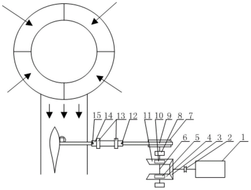
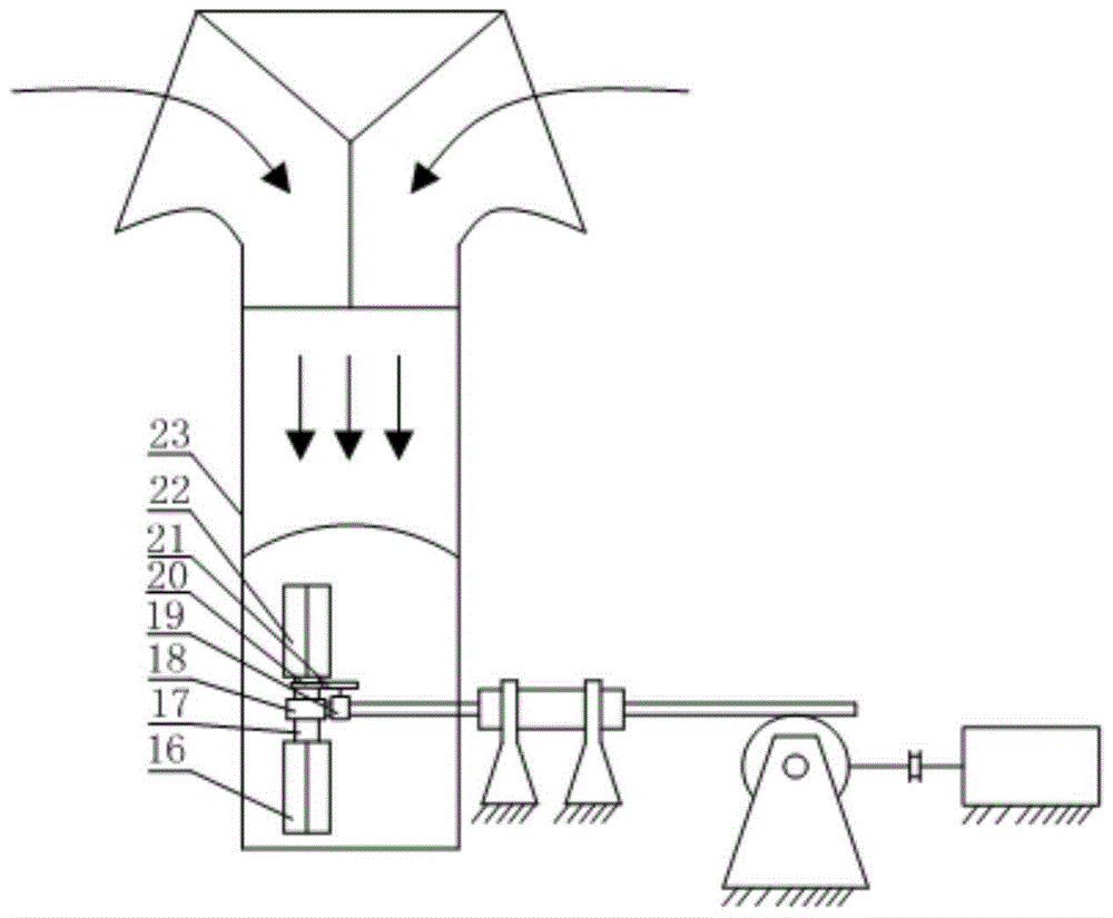
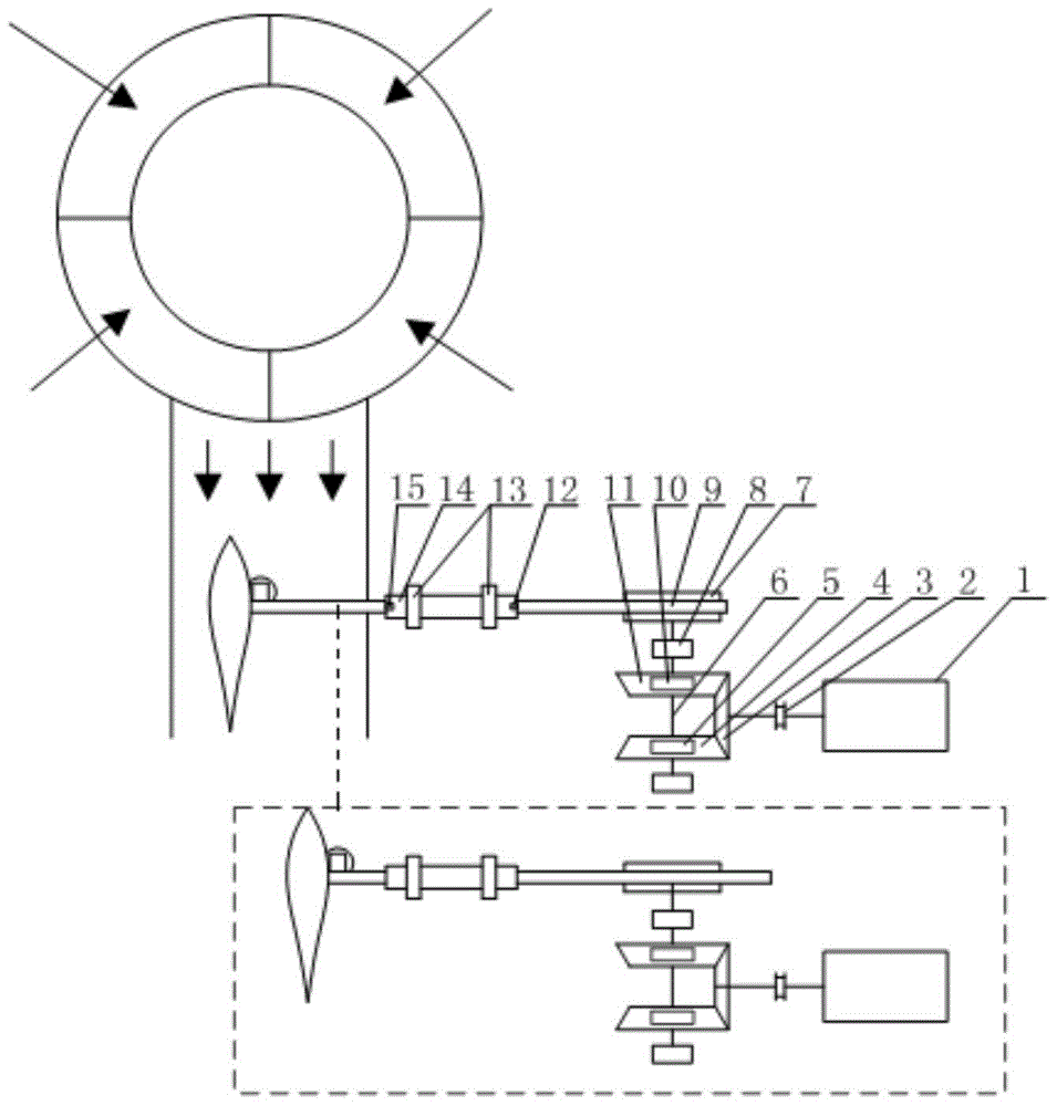
[0028] Such as figure 1 , figure 2 As shown, the wind collector 23 collects the wind energy in the atmosphere, as shown by the arrow line in the figure, the collected wind energy is blown to the upper blade 22 and the lower blade 16, and the upper blade 22 and the lower blade 16 are connected by the blade shaft 17, and the blade shaft 17 is connected to the lower blade 16. The blade bearing 18 is connected, and the blade bearing 18 is connected with the rack 9; the pitch motor 19 is installed on the rack 9, and the pitch motor 19 drives the blade shaft gear 21 to rotate through the pitch reducer 20, thereby realizing the upper blade 22 and the lower blade 16 The direction of the rack 9 is changed, and then the moving direction of the rack 9 is changed to realize the reciprocating motion of the rack 9; the rack 9 is installed in the sleeve 14, and the ...


PUM


Abstract

The invention discloses a reciprocating type wind power generation system. The reciprocating type wind power generation system comprises a wind collector, a blade system, a transmission system and a generator assembly. The wind collector collects wind energy in all directions, and transmits the wind energy to the blade system, blades of the blade system reciprocate to convert the wind energy into mechanical energy, and the blade system is connected with the generator assembly through the transmission system. The transmission system converts reciprocation movement of the blades into linear movement, the blades can reciprocate to the output end in a continuous rotation mode, and a speed increasing function of the blades is achieved. The generator assembly converts the mechanical energy into electric energy, and therefore conversion from the wind energy to the electric energy is achieved. The reciprocating type wind power generation system has the advantages of being convenient to manufacture, install and maintain, free of influences of the wind directions, capable of generating power through breezes, high in wind energy utilization rate and the like.

Description

technical field [0001] The invention relates to a reciprocating wind power generation system. Background technique [0002] With the shortage of energy and the deterioration of the ecological environment, countries around the world have generally realized the importance of new energy power generation technology, and have carried out a lot of research and development work in the fields of wind energy, nuclear energy, and solar energy. As a clean and renewable energy, wind energy has been strongly encouraged by governments of various countries and has developed rapidly. In the past 10 years, the installed capacity of wind power in the world has grown rapidly at an annual growth rate of nearly 30%, and the installed capacity of wind power in my country has grown the fastest. The country with the largest wind power installed capacity in the world. [0003] At present, the horizontal axis wind turbine is the main structural form of wind energy utilization, but the entire wind tur...

Claims


Application Information

Patent Timeline
Patent Type & Authority Patents(China)
IPC IPC(8): F03D9/25F03D15/10F03D7/06
CPCF03D3/04F03D7/06F03D9/25F05B2260/4031F05B2270/326F05B2270/602Y02E10/72Y02E10/74Y02P70/50
Inventor 杨富春
Owner SHANDONG UNIV
Learn More