
Ignition control circuit for booster of aircraft

An ignition control and control circuit technology, applied in jet propulsion devices, machines/engines, rocket engine devices, etc., can solve the problems affecting the flight safety of carrier aircraft, mission failure, low safety, etc., to improve safety and aircraft mission. The effect of reliability

Active Publication Date: 2015-03-25
JIANGXI HONGDU AVIATION IND GRP
View PDF4 Cites 10 Cited by
  • Summary
  • Abstract
  • Description
  • Claims
  • Application Information

AI Technical Summary

Problems solved by technology

This kind of ignition circuit lacks the carrier signal to participate in the control, and the safety is low. If the launch condition is not met, the aircraft will ignite the booster by mistake if the aircraft sends an ignition signal, resulting in mission failure and affecting the flight safety of the carrier aircraft.

Method used


Image

  • Ignition control circuit for booster of aircraft
  • Ignition control circuit for booster of aircraft

Examples


Embodiment

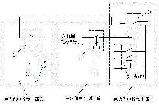
[0015] Example: see figure 1 .

[0016] A booster ignition control circuit for an aircraft, comprising an ignition power supply control circuit A, an ignition signal control circuit and an ignition power supply control circuit B, the ignition signal control circuit sends an ignition signal to the ignition power supply control circuit B, and the ignition power supply control circuit B is connected Ignition power supply circuit, ignition power supply control circuit A connects the ignition circuit to the booster 5 to ignite.

[0017] The ignition signal control circuit includes a first relay 1. The coil of the first relay 1 is controlled by the control signal C1 sent by the carrier. One side of the first relay 1 is connected to the booster ignition signal, and the other side is connected to the ignition signal. Power supply control circuit B.

[0018] The ignition power supply control circuit A includes a fourth relay 4, the coil of the fourth relay 4 is controlled by the con...


PUM


Abstract

The invention relates to the field of ignition control of aircrafts, in particular to an ignition control circuit for a booster of an aircraft. The ignition control circuit for the booster of the aircraft comprises an ignition power supply control circuit A, an ignition signal control circuit and an ignition power supply control circuit B. The ignition signal control circuit sends an ignition signal to the ignition power supply control circuit B, the ignition power supply control circuit B enables an ignition power source line to be connected, and the ignition power supply control circuit A enables the ignition power source line to be connected to the booster for ignition. The ignition control circuit for the booster of the aircraft has the advantages of improving fighter plane flying safety and task reliability of the aircraft.

Description

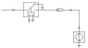
technical field [0001] The invention relates to the field of aircraft ignition control, in particular to an aircraft booster ignition control circuit. Background technique [0002] At present, the aircraft launched in the air mainly realizes the separation from the carrier aircraft through two methods of drop-in and orbital separation, so as to realize autonomous flight. Among them, the track separation method is to use the thrust generated after the booster is ignited to push the aircraft to slide on the track to realize separation from the carrier aircraft. [0003] In the previous design, the booster ignition is completed as long as the aircraft sends out the booster ignition signal. The typical ignition circuit is shown in the attached figure 2 . This kind of ignition circuit lacks the carrier signal to participate in the control, and the safety is low. If the launch conditions are not met, the aircraft will ignite the booster by mistakenly sending the ignition signal,...

Claims


Application Information

Patent Timeline
Patent Type & Authority Applications(China)
IPC IPC(8): F02K9/95
Inventor 袁飞马许立燕周志强肖光亮李科连阳刚章磊谢锦涛王俊华
Owner JIANGXI HONGDU AVIATION IND GRP
Learn More