
Water-rich sandy cobble stratum shield short-range underneath pass rigid bridge construction method

A technology of bridge construction and sand and pebbles, which is applied in basic structure engineering, earthwork drilling, soil protection, etc., can solve the problems of high labor intensity, high cost, and large engineering volume, and achieve reasonable grouting parameters and low cost , The effect of low construction cost

Active Publication Date: 2015-03-25
THE SECOND CONSTR OF CTCE GROUP
View PDF3 Cites 19 Cited by
  • Summary
  • Abstract
  • Description
  • Claims
  • Application Information

AI Technical Summary

Problems solved by technology

[0005] Under the action of groundwater in the sand and pebble formation, the rock mass is loose, without cementation, and has poor self-stabilization ability. When the cutter head rotates and cuts, the original relatively stable or balanced state of the formation is easily destroyed, and a large amount of slag pours into the cutter chamber, causing collapse at the same time , causing a large loss of formation self-stability and poor, easy to collapse after disturbance
Excessive disturbance of the bridge foundation may easily cause bridge settlement and endanger bridge safety
[0006] If the cofferdam method of traditional technology is used to strengthen the bridge abutment, the river channel will be occupied, the project volume is large, the cost is high, and the time is long. The operation will be carried out in the river channel, and the cofferdam construction will affect flood control, and there will be a greater safety risk in the rainy season.
[0007] If the traditional shield crossing bridge abutment technology is used, the bridge traffic needs to be enclosed, affecting normal use
In the shield section, the abutment foundation needs to be reinforced after grouting by deep hole grouting through the segments. The space in the shield section is narrow and the working range is limited. Deep hole grouting is difficult to operate, high in cost and labor intensive. It affects the normal excavation of the shield, and the early deformation of the bridge cannot be effectively controlled

Method used


Image

  • Water-rich sandy cobble stratum shield short-range underneath pass rigid bridge construction method
  • Water-rich sandy cobble stratum shield short-range underneath pass rigid bridge construction method
  • Water-rich sandy cobble stratum shield short-range underneath pass rigid bridge construction method

Examples


Embodiment Construction

[0027] This embodiment is a construction method of a shield tunneling under a rigid bridge in a water-rich sand and pebble stratum at a short distance. The method is as follows:

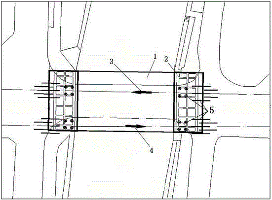
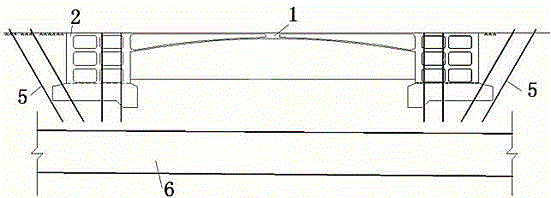
[0028] The first step is to pre-reinforce the abutment with grouting, and the abutment is reinforced with sleeve valve pipe grouting. On each side of the single-line abutment, 4 vertical holes and 5 oblique holes are set along the center line. The vertical distance between the bottom of the drilled hole and the top of the tunnel About 1.2m, use a grouting machine to inject pure cement slurry through the pre-embedded sleeve valve pipe to evenly reinforce the bottom of the abutment. The four vertical holes mentioned above have a longitudinal spacing of 2.7m, a horizontal spacing of 3m, and a hole depth of 12.8m. , 1.8m on one side and 1.2m on the other side, respectively, on both sides of the center line of the line, 4 vertical holes and 5 inclined holes are arranged on each side of the abutment; two ro...


PUM


Abstract

The invention discloses a water-rich sandy cobble stratum shield short-range underneath pass rigid bridge construction method which mainly includes the two steps of abutment grouting and pre-reinforcement and a shield tunneling technology measure. After abutment grouting and pre-reinforcement are finished, a sleeve valve pipe in an abutment is buried and constructed, and after sleeve valve pipe burying, shield construction is performed. According to the method, a related pre-reinforcement method is provided for a shield tunneling machine to pass underneath a bridge and a river in future, shield tunneling machine excavation parameters are provided, the method is economical and reasonable, operation is easy, cost is low, and technical parameters are provided for similar engineering in future.

Description

technical field [0001] The invention relates to the technical field of subway construction, in particular to a construction method for carrying out a shield tunneling under a rigid bridge at a short distance in a water-rich sandy pebble stratum. Background technique [0002] With the development of our country's economy, all major cities are constructing urban rail transit projects. In the construction of urban rail projects in cities, there are more and more bridges under the shield machine. In order to ensure the safety of bridges, feasible measures must be taken to ensure that bridges and construction safety. Our company is responsible for the construction of the shield tunneling section of the civil engineering section 7 of the first phase of Chengdu Metro Line 4 from Provincial Wenlian Station to Yushuang Road Station. The total length of the left line is 990.637m, and the total length of the right line is 1310.134m. The shield machine in this section is equipped with D...

Claims


Application Information

Patent Timeline
IPC IPC(8): E21D9/00E21D9/08E02D3/12C04B28/04
CPCE21D9/001E21D9/08
Inventor 李光强徐泽马海强
Owner THE SECOND CONSTR OF CTCE GROUP
Learn More