Thin-walled sleeve steel bar lap connection member with helical reinforcement restraint

A technology of lap joints and spiral ribs, which is applied in the direction of building components, structural elements, building reinforcements, etc., can solve the problems of weakened energy dissipation capacity of the connection position, high rigidity of the sleeve connection part, high construction and installation accuracy, etc., to achieve Improve concrete deformation ability and ductility performance, improve efficiency and quality, and facilitate the effect of grouting installation

Inactive Publication Date: 2016-08-17
SHENYANG JIANZHU UNIVERSITY
View PDF5 Cites 0 Cited by
  • Summary
  • Abstract
  • Description
  • Claims
  • Application Information

AI Technical Summary

Problems solved by technology

Disadvantages of the sleeve: 1. High precision requirements for construction and installation. Due to the use of butt joints and non-lap joints, the connection distance is short and the connection quality is difficult to guarantee. In terms of domestic construction conditions; The area moves up and decreases, which weakens the deformation and energy dissipation capacity of the connection position; 3. The amount of steel used for the sleeve is large, the price is expensive, and the economy is not good 4. The requirements for grouting materials are high, which increases the cost
Disadvantages of constrained grout-anchor lap connection: 1. The hole-forming technology is immature, and the quality of the hole is not easy to guarantee. 2. The grouting material directly contacts the concrete hole wall to absorb water, resulting in difficulty in grouting

Method used


Image

  • Thin-walled sleeve steel bar lap connection member with helical reinforcement restraint
  • Thin-walled sleeve steel bar lap connection member with helical reinforcement restraint
  • Thin-walled sleeve steel bar lap connection member with helical reinforcement restraint

Examples


Embodiment Construction

[0015] Attached below figure 1 to attach Figure 5 And the specific embodiment will further illustrate the present invention:

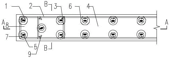
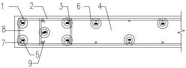
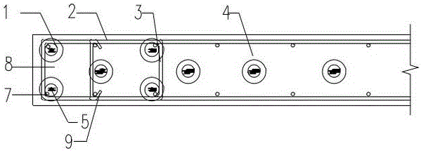
[0016] The thin-walled sleeve steel bar lap connection member with spiral reinforcement constraints is composed of the upper concrete shear wall member 4 and the lower concrete shear wall member 12, and the floor 11 is between the upper and lower prefabricated concrete shear wall members; the upper floor The concrete shear wall member 4 includes a thin-walled sleeve 1 and a spiral stirrup 6, and a thin-walled sleeve 1 is buried at the lower end of the upper concrete shear wall member 4, and the thin-walled sleeve 1 is covered with a spiral stirrup 6; the thin-walled sleeve 1 The upper and lower ends of the upper and lower ends are provided with sealing rubber plugs 13 with round holes, and the vertical steel bars 7 of the upper precast concrete shear wall extend into the thin-walled sleeve 1 through the upper end round holes; the lower concrete shear...


PUM


Abstract

The invention relates to the technical field of building concrete member manufacturing, in particular to a reinforcing bar splicing connection component comprising thin-wall sleeves constrained by spiral bars. The reinforcing bar splicing connection component comprising the thin-wall sleeves constrained by the spiral bars is applicable to connection of reinforcing bars in concrete structures and particularly applicable to connection of vertical reinforcing bars in housing-industrialized assembly-type concrete shear wall components. Reliable connection of the concrete shear wall components is achieved through the thin-wall sleeves constrained by the spiral bars and reserved extending vertical connecting reinforcing bars and by pouring high-strength grouting materials into the thin-wall sleeves. Since horizontal bars, stirrups, tie bars, spiral stirrups and the thin-wall sleeves are designed for the shear wall components, and the high-strength grouting materials are poured into the thin-wall sleeves to achieve a stable constraint effect, the compression resistance and anti-deformation capability of the concrete shear wall components is obviously improved, and the ductility performance of prefabricated concrete shear wall components is guaranteed; moreover, the lapping joint performance of the vertical steel bars can be further improved, and the shearing performance of an upper-layer shear wall and a lower-layer shear wall is well guaranteed by pouring high-strength grouting materials into a bed mortar layer.

Description

technical field [0001] The invention relates to the technical field of building concrete component manufacturing, and is suitable for the connection of steel bars in concrete structures, especially for the connection of vertical steel bars in prefabricated concrete shear wall components for residential industrialization. Background technique [0002] At present, the technical system of vertical connection in the prefabricated concrete shear wall structure in China is mainly based on sleeve connection and grout anchor lap connection. The sleeve is divided into two types: full grout sleeve and half grout sleeve, respectively. Connections are all mechanical. Disadvantages of the sleeve: 1. High precision requirements for construction and installation. Due to the use of butt joints and non-lap joints, the connection distance is short and the connection quality is difficult to guarantee. In terms of domestic construction conditions; The area moves up and decreases, which weakens...

Claims


Application Information

Patent Timeline
Patent Type & Authority Patents(China)
IPC IPC(8): E04B2/56E04C5/16
Inventor 金峤温学彬
Owner SHENYANG JIANZHU UNIVERSITY
Why Eureka
Try Eureka