
Template hoisting device

A lifting device and formwork technology, applied in the direction of transportation and packaging, load hanging components, etc., can solve the problems of manpower consumption, unbalanced force, construction accidents, etc., and achieve the effect of saving manpower, firm connection and good balance performance

Inactive Publication Date: 2015-03-25
CHONGQING DINGHAN MACHINERY
View PDF0 Cites 2 Cited by
  • Summary
  • Abstract
  • Description
  • Claims
  • Application Information

AI Technical Summary

Problems solved by technology

[0002] At present, at the construction site, various types of concrete formwork or other prefabricated formwork are often hoisted. The current formwork is hoisted by using steel wire ropes to bind the formwork, and then the steel wire rope is fixed on the hook of the crane, and then lifted by the crane. The disadvantage of this hoisting method is that it takes a lot of manpower to tie it, and it needs experienced workers to tie it firmly. If the binding is not firm, heavy objects will fall, causing construction ACCIDENT
In addition, the lifting point of the steel wire rope will affect the balance of the formwork during hoisting. If the force of the formwork is unbalanced during the hoisting process, it is also prone to problems

Method used


Image

  • Template hoisting device

Examples


Embodiment Construction

[0010] The present invention will be described in further detail below by means of specific embodiments:

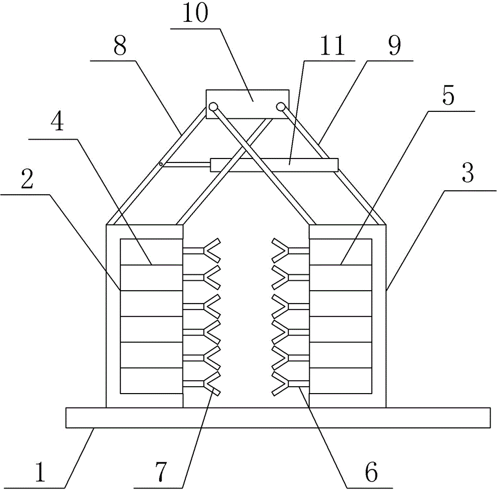
[0011] The reference signs in the drawings of the description include: base plate 1, left frame 2, right frame 3, left cylinder group 4, right cylinder group 5, piston rod 6, pneumatic gripper 7, left four-link 8, right four-link 9, hanging block 10, control cylinder 11.

[0012] The embodiment is basically shown in the accompanying drawings: the template lifting device includes a bottom plate, and a chute is installed on the surface of the bottom plate. The chute is matched with a left frame and a right frame through rollers, and the left frame and the right frame are mirror images.

[0013] There are left four-links and right four-links respectively installed above the left frame and the right frame, and the left four-links and right four-links are parallel four-bars. The lower end is hinged, the upper end of the right frame is hinged with the lower end of the right fo...


PUM


Abstract

The invention belongs to the field of load hanging elements or devices which are attached to lifting, dropping or drawing mechanisms of a crane or used for being connected with the mechanisms, and discloses a template hoisting device. The template hoisting device is matched with a lifting hook of the crane and comprises a bottom plate, wherein a sliding chute is formed in the bottom plate and is matched with a left frame and a right frame through rollers; horizontal cylinder groups are distributed in the left frame and the right frame; cylinders connected in parallel are arranged in the cylinder units; piston rods of the two cylinder groups are opposite, and pneumatic clamping jaws are fixed on the piston rods; a connecting rod structure for controlling the relative distance of the left frame and the right frame is arranged at upper ends of the left frame and the right frame, and a lifting hole allowing the lifting hook of the crane to penetrate is formed in the connecting rod structure. According to the template hoisting device, the template falling risk caused by traditional template binding is avoided, a template is directly placed in the device, manpower required by binding is saved, further, the template is placed on the bottom plate, and the balance performance in the hoisting process is better.

Description

technical field [0001] The present invention is in the field of load-hanging elements or devices attached to or intended to be connected to lifting, lowering or traction mechanisms of cranes. Background technique [0002] At present, at the construction site, various types of concrete formwork or other prefabricated formwork are often hoisted. The current formwork is hoisted by using steel wire ropes to bind the formwork, and then the steel wire rope is fixed on the hook of the crane, and then lifted by the crane. The disadvantage of this hoisting method is that it takes a lot of manpower to tie it, and it needs experienced workers to tie it firmly. If the binding is not firm, heavy objects will fall, causing construction ACCIDENT. In addition, the lifting point of the steel wire rope will affect the balance of the formwork during hoisting. If the force of the formwork is unbalanced during the hoisting process, it is also prone to problems. Contents of the invention [0...

Claims


Application Information

Patent Timeline
IPC IPC(8): B66C1/48
CPCB66C1/48
Inventor 刘文
Owner CHONGQING DINGHAN MACHINERY
Learn More