
Automobile instrument shell and backlight module

A technology of automotive instrumentation and backlight components, which is applied to vehicle components, transportation and packaging, and vehicle interior lighting devices. It can solve the problems that the LED alarm indication scheme cannot control the indicator light at the same time, cannot satisfy users, and is not humanized enough to achieve operation. and low-maintenance, sophisticated, well-conceived effects

Active Publication Date: 2015-03-25
CHONGQING YAZAKI METER
View PDF6 Cites 5 Cited by
  • Summary
  • Abstract
  • Description
  • Claims
  • Application Information

AI Technical Summary

Problems solved by technology

[0006] The car instrument display function is more and more powerful, but it only has some basic display functions, including speed, speed, fuel, water temperature and some basic information display functions of warning lights. For the needs of modern people, its traditional functions are far from Can not meet the various needs of users;
[0007] There are more and more alarm indicator lights displayed on the car instrument on the vehicle, and there are more and more display devices that need to alarm at the same time. The LED alarm indicator scheme controlled by the traditional car instrument alarm display method cannot control all the indicator lights at the same time;
[0008] The demand for car display functions is also changing. People pursue a variety of car control experiences, especially for car meters, not just a simple display background light, especially for the LCD backlight and text board of car meters, pointer brightness It used to be fixed and not humanized enough

Method used


Image

  • Automobile instrument shell and backlight module
  • Automobile instrument shell and backlight module
  • Automobile instrument shell and backlight module

Examples


Embodiment Construction

[0068] Embodiments of the present invention are described in detail below, examples of which are shown in the drawings, wherein the same or similar reference numerals designate the same or similar elements or elements having the same or similar functions throughout. The embodiments described below by referring to the figures are exemplary only for explaining the present invention and should not be construed as limiting the present invention.

[0069] Such as Figure 13 , 14 As shown in , 15, the present invention provides a car instrument housing and backlight assembly, including a strip-shaped housing 1, and two lower fixing lugs 6 arranged symmetrically on the left and right are integrally connected to the lower side of the housing 1, A first positioning hole 6a and a first through hole 6b are arranged side by side on each lower fixing lug 6, wherein the first positioning hole 6a is located at the inner end of the lower fixing lug 6, and two holes are arranged side by side ...


PUM


Abstract

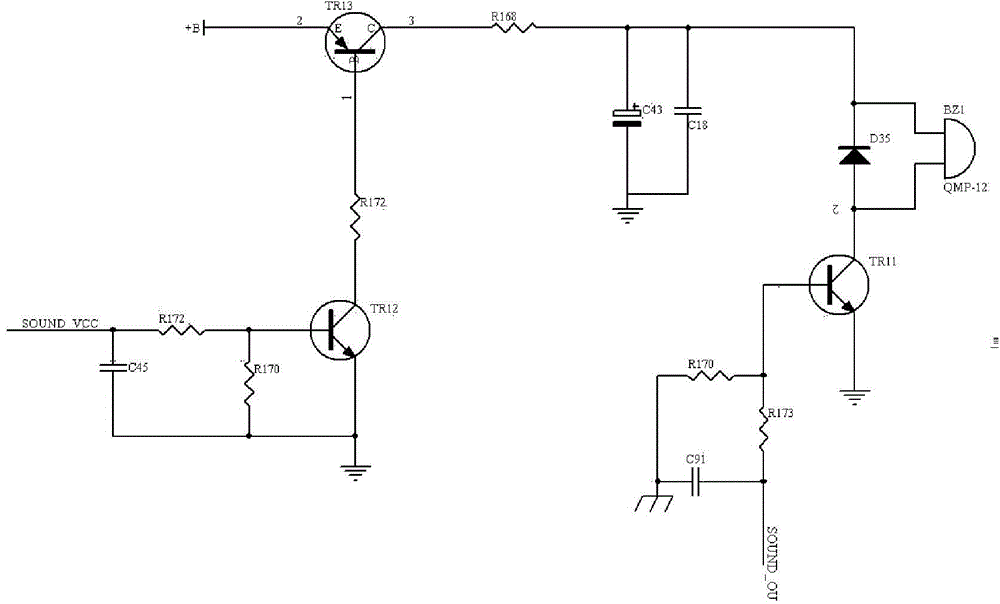
The invention discloses an automobile instrument shell and a backlight module. The backlight module comprises an anti-surge circuit, a buzzer drive circuit, a comprehensive data display circuit, a backlight adjustable circuit, an expansion indication lamp drive circuit, an anti-static device and a CPU. The output end of the anti-surge circuit is connected with the power input end of the CPU, the power input end of the buzzer drive circuit, the power input end of the comprehensive data display circuit, the power input end of the backlight adjustable circuit and the power input end of the expansion indication lamp drive circuit. The signal output end of the comprehensive data display circuit is connected with the signal input end of the backlight adjustable circuit, the buzzer signal output end of the comprehensive data display circuit is connected with the signal input end of the buzzer drive circuit, the indication lamp signal output end of the comprehensive data display circuit is connected with the signal input end of the expansion indication lamp drive circuit, and the signal output end of the expansion indication lamp drive circuit is connected with the signal input end of the backlight adjustable circuit.

Description

technical field [0001] The invention relates to the field of electronic circuits, in particular to an automobile instrument casing and a backlight assembly. Background technique [0002] In the prior art, there is no structure for directly installing the backlight assembly on the automobile instrument casing, and the backlight assembly is directly installed on the PCB assembly, while the PCB assembly is installed in the casing, and the casing is opened at the position facing the backlight assembly. To make way for the gap, a screen panel is also installed on the casing, and an LCD window is opened on the screen panel, and the LCD window is facing the LCD display area of ​​the backlight assembly. In this way, the backlight assembly is positioned through the PCB assembly, while the screen panel is positioned through the housing. Due to inconsistent positioning references, it is very easy to cause the LCD display area on the backlight assembly and the LCD window on the screen p...

Claims


Application Information

Patent Timeline
IPC IPC(8): B60K35/00B60Q3/04
Inventor 梁东生伍跃洪唐彦杰刘益
Owner CHONGQING YAZAKI METER
Learn More