
Cambered surface clamping device

A clamping and cambered technology, applied in the workpiece clamping device, positioning device, clamping and other directions, can solve the problem of difficult positioning of the device

Inactive Publication Date: 2015-03-25
常州市品鑫除尘设备有限公司
View PDF0 Cites 7 Cited by
  • Summary
  • Abstract
  • Description
  • Claims
  • Application Information

AI Technical Summary

Problems solved by technology

[0002] In the production and manufacturing, the positioning of the circular material is carried out by the device with the clamping surface as the arc surface. In the positioning of the traditional device with the clamping surface as the arc surface, the positioning surfaces of the two clamping surfaces are corresponding. However, when the two sides of the circular material are different, it is difficult for the traditional device to position stably.

Method used


Image

  • Cambered surface clamping device

Examples


Embodiment Construction

[0011] The present invention will be further described in detail below in conjunction with the accompanying drawings and specific embodiments.

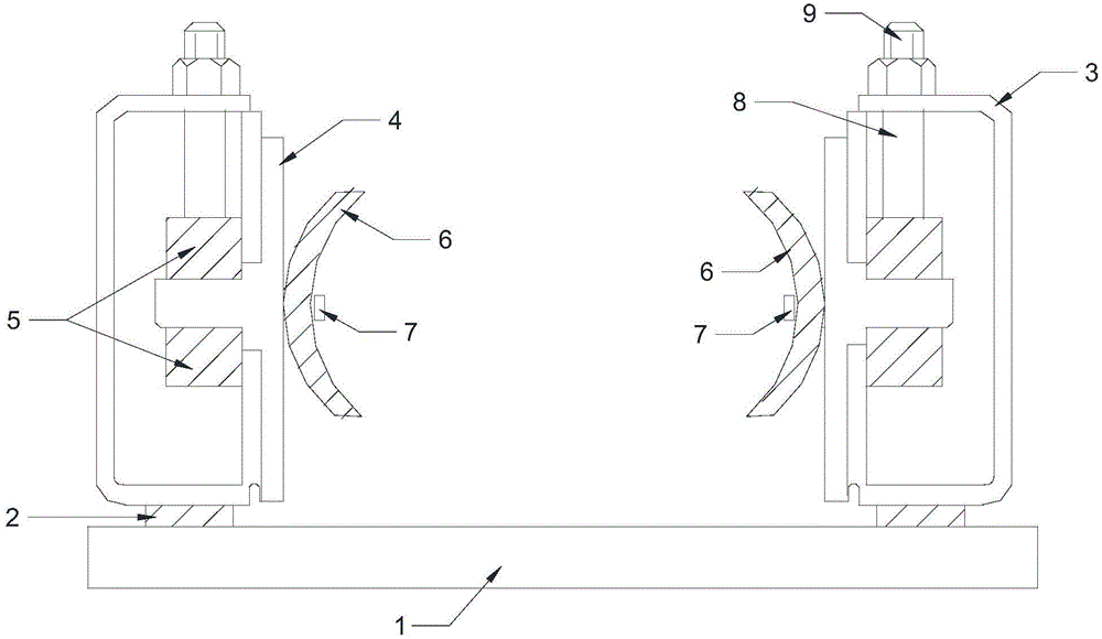
[0012] The arc surface clamping device includes a horizontal work table 1, and plane bearings 2 are symmetrically arranged at both ends of the horizontal work table 1, and also includes a rectangular frame 3 connected to the plane bearing 2. Through the plane bearings, the rectangular frame can realize horizontal Rotation in the vertical plane of the face on which the work table is located;

[0013] The rectangular frame is provided with a through hole on the side wall perpendicular to the horizontal work table, and the opening direction of the through hole is parallel to the plane where the horizontal work table is located;

[0014] Also comprise clamping part, described clamping part comprises T-shaped movable plate 4, the vertical end of described T-shaped movable plate 4, namely is connected in the end that is connected at the cen...


PUM


Abstract

The invention relates to the field of fittings, in particular to a cambered surface clamping device. The cambered surface clamping device comprises a horizontal operating table top, wherein plane bearings are symmetrically arranged at two ends of the horizontal operating table top; the cambered surface clamping device further comprises a rectangular framework connected with the plane bearings; a through hole is formed in the side wall, perpendicular to the horizontal operating table top, of the rectangular framework; the cambered surface clamping device further comprises a T-shaped removable plate; the vertical end of the T-shaped removable plate is inserted into the through hole and positioned in the rectangular framework; a rotating nut is arranged in the rectangular framework; the rotating nut is rotationally connected with the vertical end of the T-shaped removable plate; an arc clamping plate is arranged on the surface of the horizontal end of the T-shaped removable plate. The invention aims at providing a cambered surface clamping device which can be fit for the positioning of regular cambered surface work pieces or irregular cambered surfaces, with improved application range and practicability.

Description

technical field [0001] The invention relates to the field of tool accessories, in particular to an arc clamping device. Background technique [0002] In the production and manufacturing, the positioning of the circular material is carried out by the device with the clamping surface as the arc surface. In the positioning of the traditional device with the clamping surface as the arc surface, the positioning surfaces of the two clamping surfaces are corresponding. However, when the curved surfaces of the two sides of the circular material are different, it is difficult for the traditional device to position stably. Contents of the invention [0003] The object of the present invention is to propose a curved surface clamping device, which can adapt to the positioning of regular curved surface workpieces or irregular curved surface workpieces, has improved application range and is practical. [0004] The technical scheme that realizes the object of the present invention is as...

Claims


Application Information

Patent Timeline
Patent Type & Authority Applications(China)
IPC IPC(8): B23Q3/06B25B11/00
CPCB23Q3/062B25B11/00
Inventor 陈文娟
Owner 常州市品鑫除尘设备有限公司
Learn More