
Thick plate continuous blanking mold

A technology of blanking dies and dies, applied in the field of stamping dies, can solve the problems of large mold structure and low production efficiency, and achieve the effects of improving stamping processing efficiency, occupying less space, and facilitating design and implementation

Active Publication Date: 2017-02-22
GREAT WALL MOTOR CO LTD
View PDF9 Cites 0 Cited by
  • Summary
  • Abstract
  • Description
  • Claims
  • Application Information

AI Technical Summary

Problems solved by technology

However, in the stamping production of this mold structure, each process needs to use a separate mold, which will result in a large number of mold structures, and there is also a problem of low production efficiency due to the connection interval between the mold structures

Method used


Image

  • Thick plate continuous blanking mold
  • Thick plate continuous blanking mold
  • Thick plate continuous blanking mold

Examples


Embodiment Construction

[0032] It should be noted that, in the case of no conflict, the embodiments of the present invention and the features in the embodiments can be combined with each other.

[0033] The present invention will be described in detail below with reference to the accompanying drawings and examples.

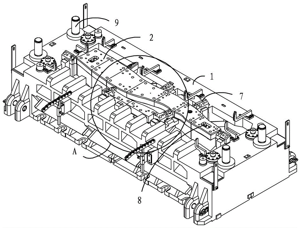
[0034] This embodiment relates to a thick plate continuous blanking die, such as Figure 1 to Figure 6 As shown in , it includes a lower mold base 1 with a punch 2, and an upper mold base 11 with a die 12 corresponding to the punch 2 on the lower mold base 1, which can use the upper mold base 11 The relative movement between the die 12 and the punch 2 on the lower mold base 1 is used to process the product.

[0035] The specific structure of the lower mold base 1 is as follows: figure 1 and figure 2 As shown in , the punch 2 is arranged in the middle of the lower die base 1, and the punch 2 can be designed in any shape according to the configuration of the required plate. As in this ...


PUM


Abstract

The invention provides a continuous punching die of a thick plate. The continuous punching die is provided with a lower die seat with a male die body and an upper die seat with a female die body corresponding to the male die body. A product is machined through relative movement of the male die body and the female die body, and a trimming insert fixedly arranged on the upper die seat, a trimming female die body fixedly arranged on the upper die seat and a shape cutting insert fixedly arranged on the lower die seat are further included. The trimming insert is provided with a matching edge matched with one side of a die cavity of the female die body and a shape correction edge following up the shape of the other side of the die cavity of the female die body. A die cavity of the trimming female body is provided with a die cavity edge matched with the shape correction edge of the trimming insert. The shape cutting insert is provided with a trimming male die body, a first insert and a second insert, the trimming male die body corresponds to the trimming female die body in shape and position, and the first insert and the second insert are connected between the trimming male die body and the male die body. According to the continuous punching die of the thick plate, multiple procedures can be achieved on the single die structure, and therefore the die quantity is saved, and production efficiency is improved.

Description

technical field [0001] The invention relates to the technical field of stamping dies, in particular to a thick plate continuous blanking die. Background technique [0002] With the development of stamping technology, the material utilization rate and production efficiency of stamping dies have become a great obstacle restricting the development of stamping technology. For traditional thick plates (the thickness of the plate is greater than 1.5mm), due to the thickness of the plate, it is impossible to use the uncoiler line for mass production, and it is usually produced with a mold structure that falls one piece at a time. However, in the stamping production of this mold structure, each process needs to use a separate mold, which will result in a large number of mold structures, and also has the problem of low production efficiency due to the generation of connection intervals between the mold structures. Contents of the invention [0003] In view of this, the present inv...

Claims


Application Information

Patent Timeline
Patent Type & Authority Patents(China)
IPC IPC(8): B21D28/14B21D28/04
CPCB21D28/04B21D28/14
Inventor 魏国哲王之来樊倩石朋飞
Owner GREAT WALL MOTOR CO LTD
Learn More