
Gastrointestinal decompression device

A technology of gastrointestinal decompression and gastric tube, which is applied in the direction of catheters, other medical devices, suction devices, etc., which can solve the cumbersome cleaning of devices, the short time to remove the gastrointestinal decompressor, and affect the breathing and nursing work of personnel in the ward etc. to achieve the effect of convenient operation, avoiding pollution and simple structure

Inactive Publication Date: 2015-03-25
张华平
View PDF0 Cites 2 Cited by
  • Summary
  • Abstract
  • Description
  • Claims
  • Application Information

AI Technical Summary

Problems solved by technology

[0003] The structure and function of the gastrointestinal decompressor in the prior art are too simple, and it cannot prevent the pollution of the aspirate, and the cleaning of the equipment is also very cumbersome, which brings a lot of inconvenience to the medical care work
The fluid drained from the gastrointestinal decompression device must be continuously poured out and the amount of liquid must be calculated. Because the patient’s gastrointestinal decompression is continuous, the time for taking off the gastrointestinal decompressor is short, so the accompanying staff can only quickly decompress the gastrointestinal tract. The liquid in the depressor is dumped into the spittoon beside the bed or in the indoor toilet. Due to the unpleasant smell of the drainage fluid, it seriously affects the breathing and nursing work of the personnel in the ward.
At the same time, the traditional gastrointestinal decompression can only be used as an adjuvant treatment by observing the properties and volume of the drainage, and cannot observe the gastrointestinal conditions in a dynamic manner.

Method used


Image

  • Gastrointestinal decompression device

Examples


Embodiment Construction

[0012] The specific embodiments of the present invention are given below with reference to the accompanying drawings, which are used to further describe the structure of the present invention.

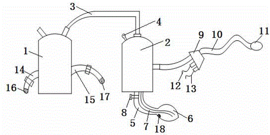
[0013] A gastrointestinal decompression device of this embodiment includes a ventilator 1 and an absorption bottle 2, the top of the ventilator 1 and the absorption bottle 2 are connected by a hose 3, and a pressure gauge 4 is provided on the upper part of the absorption bottle 2 for timely observation Absorbing the internal pressure of the bottle body 2, the bottom of the absorbing bottle body 2 is fixedly connected with a rubber tube 5, and the rubber capsule 6 is detachably socketed on the rubber tube 5, and the inner cavity of the rubber tube 5 is provided with a conduit 7 and extends to the bottom of the rubber capsule 6, The inner side of the top of the rubber capsule 6 is provided with a sensor 18. When the volume of the aspirate reaches the position of the sensor 18, the sensor ...


PUM


Abstract

The invention relates to a gastrointestinal decompression device, and belongs to the technical field of structures of medical instruments. The gastrointestinal decompression device comprises a breathing machine and an absorption bottle body; the breathing machine is connected with the top end of the absorption bottle body through a hose; a pressure meter is arranged at the upper portion of the absorption bottle body; a rubber tube is fixedly connected to the bottom of the absorption bottle body; a catheter is arranged in an inner cavity of the rubber tube and extends to the bottom of a rubber capsule; an inducer is arranged on the inner side of the top end of the rubber capsule, and a valve is installed on the catheter; the lateral side of the absorption bottle body is connected with a stomach tube through a three-way connector; the other end of the stomach tube is provided with a capsule endoscope; and a lead screw and a connecting line are connected with the capsule endoscope through the stomach tube. The gastrointestinal decompression device is simple in structure and convenient to operate; and suction-out objects are stored in the rubber capsule, the rubber capsule is replaced in time to enable the suction-out objects to be specially processed in a unified mode, and therefore pollution of the suction-out objects is avoided. Meanwhile, the capsule endoscope is arranged, so that a medical worker observes the gastrointestinal decompression conditions in time, and smooth implementation of gastrointestinal decompression is facilitated.

Description

[0001] technical field [0002] The invention relates to a gastrointestinal decompression device, which belongs to the technical field of medical device structures. Background technique [0003] The structure and function of the gastrointestinal decompressor in the prior art are too simple, and the pollution of the aspirate cannot be prevented, and the cleaning of the equipment is also very complicated, which brings a lot of inconvenience to the medical care work. The fluid drained from the gastrointestinal decompression device must be continuously poured out and the amount of liquid must be calculated. Because the patient’s gastrointestinal decompression is continuous, the time for taking off the gastrointestinal decompressor is short, so the accompanying staff can only quickly decompress the gastrointestinal tract. The liquid in the pump is dumped into the spittoon beside the bed or in the indoor toilet. The unpleasant smell of the drainage fluid seriously affects the br...

Claims


Application Information

Patent Timeline
IPC IPC(8): A61M1/00A61M25/00
CPCA61M1/00A61M2210/1042
Inventor 张华平
Owner 张华平
Learn More