
Filter

A filter and ring resonator technology, applied in the field of communication, can solve the problems of narrow stopband bandwidth, large size, uncontrollable, etc.

Active Publication Date: 2015-03-18
ZTE CORP
View PDF2 Cites 8 Cited by
  • Summary
  • Abstract
  • Description
  • Claims
  • Application Information

AI Technical Summary

Problems solved by technology

The main disadvantages of the above methods include narrow and uncontrollable stopband bandwidth, complex processing, large size, and inconvenient expansion to achieve multi-stopband characteristics. Therefore, a new type of notch structure is needed to solve at least one of the above problems. one

Method used

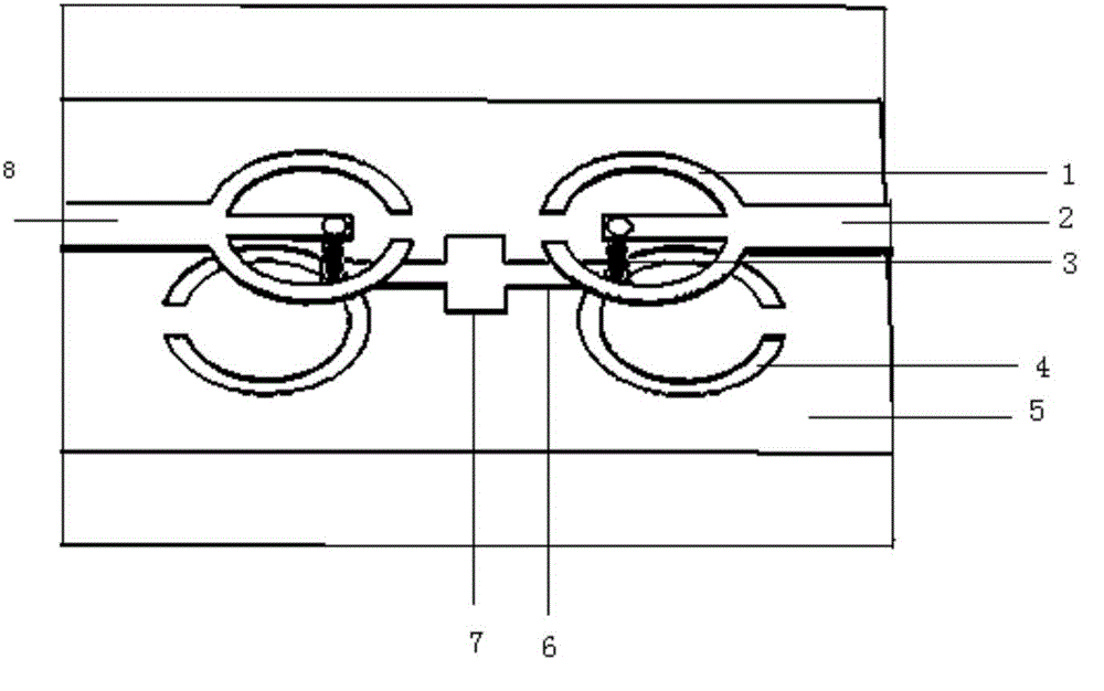
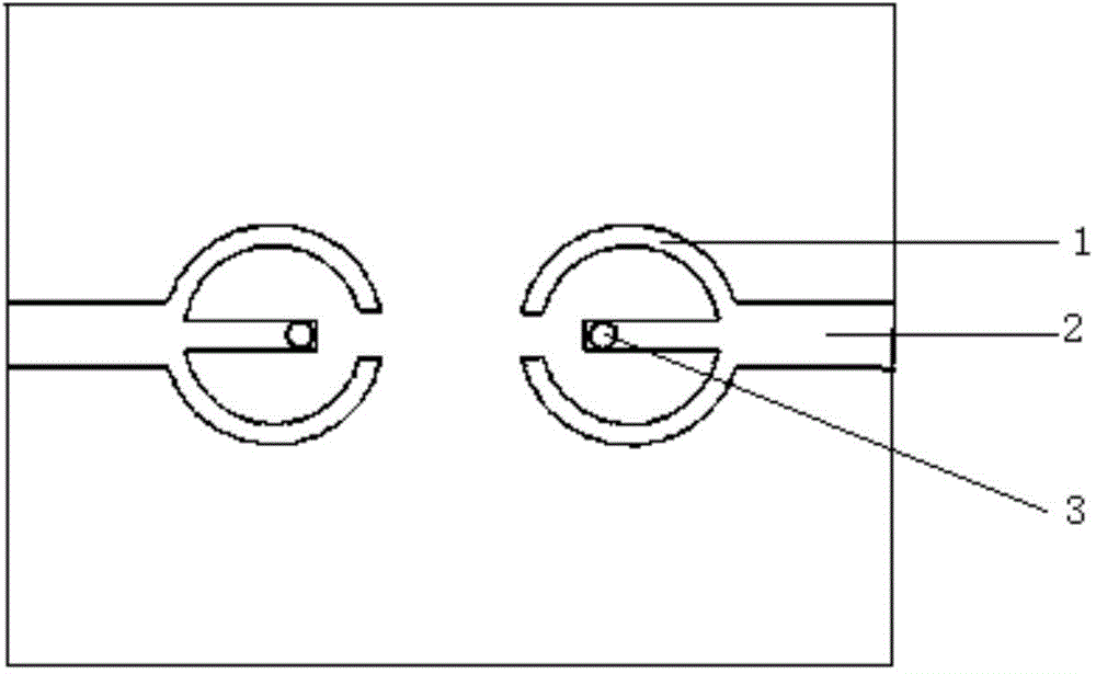

Image

  • Filter
  • Filter
  • Filter

Examples


Embodiment Construction

[0022] It should be noted that, in the case of no conflict, the embodiments in the present application and the features in the embodiments can be combined with each other. The present invention will be described in detail below with reference to the accompanying drawings and examples.

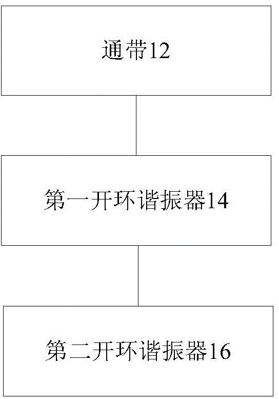
[0023] In this embodiment, a filter is provided, figure 1 is a structural block diagram of a filter according to an embodiment of the present invention, such as figure 1 As shown, the structure includes: a passband 12 , a first split-loop resonator 14 and a second split-loop resonator 16 .

[0024] a passband 12 located between the first split-loop resonator 14 and the second split-loop resonator 16;

[0025] The first open-loop resonator 14 is arranged above the passband 12, the first open-loop resonator 14 includes a first loop and a second loop, and openings are provided on the first loop and the second loop;

[0026] The second open-loop resonator 16 is arranged below the passband 12. Th...


PUM


Abstract

Disclosed is a filter. The filter comprises: a passband; a first open-loop resonator which is arranged above the passband, the first open-loop resonator comprising a first loop band and a second loop band, and both the first loop band and the second loop band being respectively provided with an opening thereon; and a second open-loop resonator which is arranged below the passband, the second open-loop resonator comprising a third loop band and a fourth loop band, and both the third loop band and the fourth loop band being respectively provided with an opening thereon, wherein the first loop band and the third loop band form a complementary open-loop resonator, and the second loop band and the fourth loop band form a complementary open-loop resonator. By means of the present invention, at least one of the problems existing in a filter in the prior art is solved, and a relatively excellent filter is provided.

Description

technical field [0001] The present invention relates to the communication field, in particular to a filter. Background technique [0002] In a communication system, filters generally exist between the input and output stages of active circuits, and each filter has its own different functions. The filter is an indispensable device in the wireless communication system, and its performance is directly related to the communication quality of the entire system. The functions of the filter include: avoiding saturating the receiver front-end due to leakage of the output signal at the transmitter; removing interfering signals such as images; reducing power leakage from the local oscillator at the antenna; and attenuating the simultaneous presence of different communications interference between systems, etc. Therefore, it must have characteristics such as steep rise, fall edge attenuation, and good group delay. [0003] With the development of wireless communication, filter resea...

Claims


Application Information

Patent Timeline
Patent Type & Authority Applications(China)
IPC IPC(8): H01P1/20H01P1/203
CPCH01P1/20381
Inventor 蔡凌云刘洋
Owner ZTE CORP
Learn More