
Linear illuminants with special-shaped cross-section

A linear light-emitting, special-shaped cross-section technology, applied in the direction of light guide, electric light source, light source fixation, etc. of the lighting system, can solve the problems of interlayer peeling, light leakage, leakage, etc., and achieve the effect of reducing leakage

Active Publication Date: 2017-04-12
FUKUBI KAGAKU IND
View PDF13 Cites 0 Cited by
  • Summary
  • Abstract
  • Description
  • Claims
  • Application Information

AI Technical Summary

Problems solved by technology

[0006] However, in the linear luminous body of the above-mentioned prior art, since the protrusions and grooves are only formed by shaping the outer covering layer into a deformed cross section, the thickness of the outer covering layer becomes locally large, and there is a part where the light becomes easy to pass through. Leaked Cons
Therefore, a large part of the light leaks from the mounting surface side (the side opposite to the visible surface) of the linear light emitter, and it is impossible to make the linear light emitter emit light in a well-balanced manner from the light source to a distant position.
[0007] Moreover, the above-mentioned prior art linear luminous body, because it is installed on the object to be fixed in a bent state, only the outside of the object to be fixed is inserted or locked in the concave portion of the object to be fixed. The cladding (protrusion) has a structure that applies a load in the bending direction, so delamination easily occurs between the cladding that receives a direct load from the object to be fixed and the core that indirectly receives a load from the cladding

Method used


Image

  • Linear illuminants with special-shaped cross-section
  • Linear illuminants with special-shaped cross-section
  • Linear illuminants with special-shaped cross-section

Examples


Embodiment 1

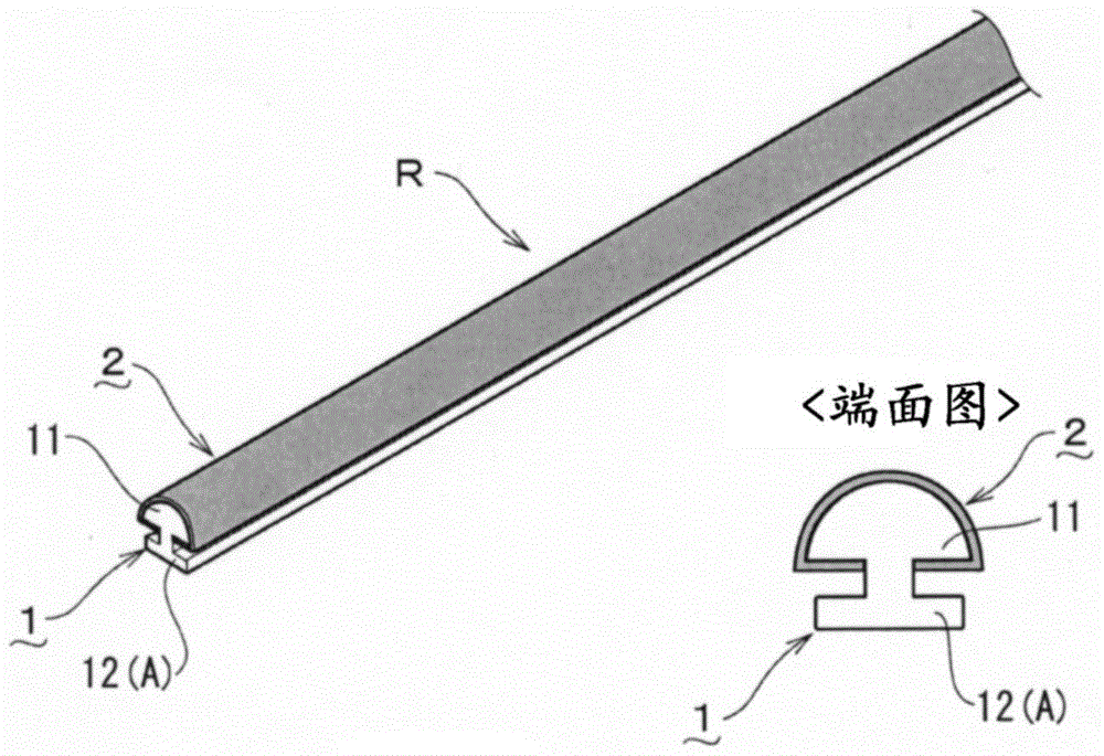
[0041] according to figure 1 and figure 2 Example 1 of the present invention will be described. In addition, in this figure, a portion indicated by reference numeral 1 is a core layer, and a portion indicated by reference numeral 2 is an outer cladding layer.

[0042] Composition of linear illuminants

[0043] First, in Example 1, an outer cover layer 2 made of a translucent resin is formed to cover an arbitrary portion desired to emit light on the surface of a core layer 1 made of a transparent resin, thereby constituting a luminous body R (refer to figure 1 ). In addition, the core layer 1 is formed into a profiled cross-sectional shape, forming a semicircular cross-sectional light-guiding portion 11 and a cross-sectional T-shaped rib-shaped protrusion 12 formed on the planar portion of the light-guiding portion 11 .

[0044]In addition, in this embodiment, PMMA (polymethyl methacrylate) with a refractive index of 1.49 is used for the material of the core layer 1, and t...

Embodiment 2

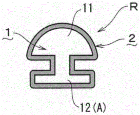
[0056] Below, according to image 3 Example 2 of the present invention will be described. In this Example 2, the overcoat layer 2 is formed on the entire surface of the core layer 1 having a shaped cross-section similar to that of the Example 1, thereby constituting the main body R of the luminous body. Thereby, the cover layer 2 of the attachment part A can be formed thinner than the conventional one, and therefore, the leakage of light from the mounting surface side of the luminous body main body R can be suppressed.

[0057] In addition, by forming the outer cover layer 2 in a cylindrical shape over the entire surface of the core layer 1 as described above, since the outer cover layer 2 has a ring shape, there is no problem that the outer cover layer 2 peels off from the end. Also, even when the luminous body R is attached to the fixed object F in a bent state, since the load is not applied only to the outer cover layer 2, delamination is less likely to occur.

Embodiment 3

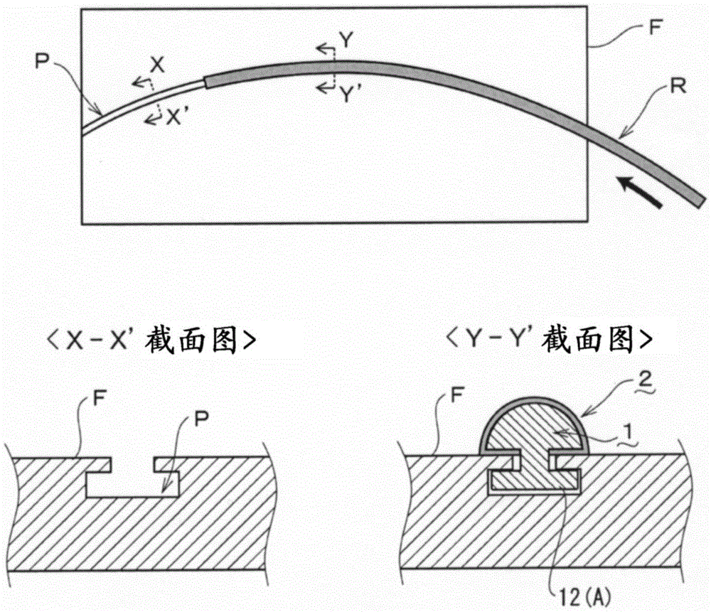
[0059] Below, according to Figure 4 and Figure 5 Embodiment 3 of the present invention will be described. In this embodiment 3, the core layer 1 protrudes from the semicircular cross-sectional shape of the main light-emitting portion 11 with an arrow-shaped tendon-shaped protruding portion 12 to form the attachment portion A of the luminous body R ( Figure 4 reference). Thus, if Figure 5 (a) As shown in (b), the attachment part A can be pushed into the recess P of the fixed object F in the depth direction of the groove, and the luminous body R can be fixed on the fixed object F.


PUM


Abstract

PROBLEM TO BE SOLVED: To provide an irregular shaped cross section linear light emitter that allows quick attaching operation to a fixture object, further prevents removal from an attachment surface and interlayer peeling between a core layer and a cladding layer in attachment, and that can emit well-balanced light across a portion away from an end where a light source is arranged.SOLUTION: A light emitter body R of a linear light emitter attached and fixed to a recess or a salient of a fixture object F comprises: a core layer 1 made of a transparent resin having a refractive index larger than that of the air; and a cladding layer 2 made of a translucent resin having a refractive index smaller than that of the core layer 1 and larger than that of the air, and formed so as to cover any portion for emitting light on the surface of the core layer 1. An attachment portion A capable of being attached to the recess or the salient of the fixture object F is formed by moulding the core layer 1 into an irregular shaped cross section including a stripe-like projection part 12 or a groove part.

Description

technical field [0001] The present invention relates to the improvement of a linear illuminant, in particular, to a linear illuminant with a special-shaped cross-section, which can not only be easily installed with respect to the fixed object, but also The peeling of the core layer and the cladding layer is also less likely to occur during mounting, and light can be emitted in a well-balanced manner from the end where the light source is placed to a remote location. Background technique [0002] As we all know, most of the colorful lights and lighting signs use linear illuminants like neon lights. The neon lights made of glass tubes cannot bend the linear illuminants along the wall because the illuminants themselves are not flexible. The bending part attaches or bends the linear luminous body to draw pictures and characters. [0003] Therefore, an optical fiber-type linear light-emitting body has been developed in the past. The fiber-optic linear light-emitting body has fle...

Claims


Application Information

Patent Timeline
Patent Type & Authority Patents(China)
IPC IPC(8): F21S4/00F21V5/00F21V13/04
CPCF21V5/00F21V13/04F21V7/10F21V17/16F21V19/009G02B6/0001
Inventor 金森尚哲小林俊幸
Owner FUKUBI KAGAKU IND
Learn More