
Intelligent industrial dust collector

An industrial vacuum cleaner and intelligent technology, applied in the installation of vacuum cleaners, electrical equipment, cleaning equipment, etc., can solve the problems of poor factory environment, inconvenient movement, low work efficiency, etc., and achieve a high degree of automation, high work efficiency, and intuitive observation. Effect

Inactive Publication Date: 2015-03-18
吴坚
View PDF1 Cites 1 Cited by
  • Summary
  • Abstract
  • Description
  • Claims
  • Application Information

AI Technical Summary

Problems solved by technology

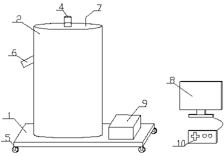
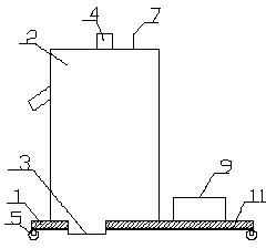
[0002] Industrial vacuum cleaner is a kind of equipment commonly used in industry. It is used to collect waste, filter and purify air, and clean the environment during industrial production. It is widely used in textile and The chemical industry can prevent the hazards of some occupational diseases. At present, China's industry is developing rapidly, and the annual industrial output value is constantly increasing. Therefore, the demand for personnel is also increasing. However, the factory environment is generally poor, and there is a lot of dust and waste. It has an impact on the health of workers. The application number is CN201120237688.7, which discloses an industrial vacuum cleaner, including a box body, and an exhaust fan is arranged in the box body, and the exhaust fan is connected with an inlet through a ventilation duct Air outlet, the other end of the exhaust fan is connected with an air outlet, the air inlet and outlet are located on the box, the air inlet is connected to a filter assembly, and the filter assembly is located In the box, the filter assembly is fixed on the box. The invention provides an industrial vacuum cleaner with simple structure, strong suction, not easy to damage, and easy to clean; it solves the problem of insufficient suction and inconvenient cleaning of industrial vacuum cleaners in the prior art , the technical problem of complex equipment structure, but the equipment requires manual on-site operation. For a relatively large factory building, it takes a lot of physical strength of the workers, the work efficiency is not high, and it is inconvenient to move and the degree of automation is not high.

Method used


Image

  • Intelligent industrial dust collector
  • Intelligent industrial dust collector

Examples


Embodiment Construction

[0012] In order to make the technical means, creative features, goals and effects achieved by the present invention easy to understand, the present invention will be further described below in conjunction with specific embodiments.

[0013] refer to figure 1 with figure 2 , an intelligent industrial vacuum cleaner in this embodiment can transmit the image in the factory building to the monitoring system through the probe provided at the front end of the cylinder, and the staff will send a signal to the receiving antenna through the control device connected to the monitoring system, and then The power device on the control bracket makes the industrial vacuum cleaner move to clean the dust and waste in the factory. The device is easy to operate and intuitive to observe. It does not need to consume a lot of physical strength of the workers. It has high work efficiency, is convenient to move, and has a high degree of automation. , including a bracket 1 and a cylinder 2 installed...


PUM


Abstract

The invention discloses an intelligent industrial dust collector which comprises a bracket and a barrel mounted on the bracket, wherein an air inlet is arranged in the bottom of the barrel; an air outlet is arranged in the top of the barrel; idler wheels are arranged at the bottom of the bracket; a monitoring detector is arranged at the front end of the barrel; a receiving antenna is arranged at the top of the barrel; the receiving antenna is connected with a monitoring system; the length of the receiving antenna is 10cm; a power device is arranged on the bracket; the power device is connected with the idler wheels. The intelligent industrial dust collector has the advantages of convenience in control, direct observation, no need of consuming a large amount of physical power, high working efficiency, convenience in moving, high degree of automation and high popularization value.

Description

technical field [0001] The invention relates to the industrial field, in particular to an intelligent industrial vacuum cleaner. Background technique [0002] Industrial vacuum cleaner is a kind of equipment commonly used in industry. It is used to collect waste, filter and purify air, and clean the environment during industrial production. It is widely used in textile and chemical industries to prevent some occupational diseases. At present, China's industry is developing rapidly. , the annual industrial output value is constantly increasing, so the demand for personnel is also increasing, but the factory environment is generally poor, there is a lot of dust and waste, which affects the health of workers, the application number is CN201120237688. 7 discloses an industrial vacuum cleaner, which includes a box body. An exhaust fan is arranged in the box body. The exhaust fan is connected to an air inlet through an air duct, and the other end of the exhaust fan is connected ...

Claims


Application Information

Patent Timeline
Patent Type & Authority Applications(China)
IPC IPC(8): A47L5/00A47L9/00A47L9/28
Inventor 吴坚
Owner 吴坚
Learn More