
Method for adjusting DDR working frequency through television demodulation SOC

A technology of working frequency and chip, which is applied in the field of TV demodulation SOC chip to adjust the working frequency of DDR, which can solve the problems of inability to adjust and achieve the effect of improving performance and reducing input noise

Active Publication Date: 2015-03-11
HANGZHOU NATCHIP SCI & TECH
View PDF5 Cites 6 Cited by
  • Summary
  • Abstract
  • Description
  • Claims
  • Application Information

AI Technical Summary

Problems solved by technology

Since the video output clock must meet the video output standard, the frequency of the external crystal oscillator input clock must be kept constant and cannot be adjusted according to the method described in patent CN201320003017.3
The interference generated by the DDR clock in the TV demodulation SOC chip is an important interference faced by the channel demodulation module
The DDR clock is independent of the clock of the channel demodulation module, and it is impossible to reduce the interference generated by the DDR clock by adjusting the clock of the channel demodulation module according to the method described in patent CN201320003017.3

Method used


Image

  • Method for adjusting DDR working frequency through television demodulation SOC
  • Method for adjusting DDR working frequency through television demodulation SOC

Examples


Embodiment Construction

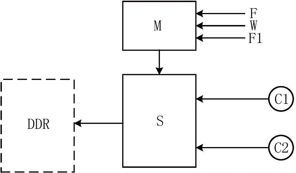
[0017] A method for adjusting DDR operating frequency by a television demodulation SOC chip, the method adopts a clock selector, a control state machine and two DDR clock sources. The control state machine generates the optimal selection signal according to the center frequency point F of the frequency band to be demodulated and the safe frequency point distance W; the control state machine controls the clock selector to select one of the two DDR clock sources as the DDR clock signal output ; The specific method is:

[0018] The center frequency point F of the frequency band to be demodulated and the safe frequency point distance W are used as two inputs of the control state machine, and the control state machine calculates the lower frequency point Fd to be protected and the upper frequency point to be protected according to F and W Fu, the frequency band greater than Fd and less than Fu is the frequency band to be protected; Fd=F-W, Fu=F+W;

[0019] Select two DDR clock sou...


PUM


Abstract

The invention relates to a method for adjusting DDR (Double Data Rate SDRAM) working frequency through a television demodulation SOC (System On Chip). When television signals are demodulated, interference caused by DDR action is transmitted to a channel demodulation module to reduce performance of the channel modulation module. The DDR working frequency chip adjusting method disclosed by the invention adopts a clock selector, a control state machine and two DDR clock sources, wherein the control state machine generates optimal selection signals according to a central frequency point F of a frequency band to be demodulated and a safe frequency point distance W; the control state machine controls the clock selector to select one of the two DDR clock sources as a signal output of DDR clocks. According to the method, a clock source selecting function to DDR is added in the television demodulation SOC chip, so that interference signals caused by DDR can be removed from a specific frequency band when a television program transmitted within the specific frequency band is demodulated, so as to reduce input noise of the channel demodulation module and improve properties of the channel demodulation module.

Description

technical field [0001] The invention belongs to the technical field of integrated circuits, and relates to a method for adjusting a DDR operating frequency by a television demodulation SOC chip. Background technique [0002] DDR SDRAM (Double Speed ​​Synchronous Dynamic Random Access Memory, referred to as DDR) is an important peripheral of the SOC (System On Chip, System On Chip) chip. The DDR interface has a high operating frequency and a large operating current, which will cause high conduction interference and radiation interference on the chip and circuit system. If the frequency band of the interference caused by DDR is not within the frequency band of the input signal of the sensitive circuit of the SOC, usually this interference will not affect the performance of the SOC. [0003] The TV demodulation SOC chip refers to the SOC that includes the TV transmission channel demodulation module. Commonly used TV channel demodulation modules include cable TV transmission s...

Claims


Application Information

Patent Timeline
Patent Type & Authority Applications(China)
IPC IPC(8): H04N21/426H04N5/455
CPCH04N21/42615H04N21/42676
Inventor 梁骏黄凤娇沈建强夏宝林
Owner HANGZHOU NATCHIP SCI & TECH
Learn More