Ventilating slot structure of generator rotor
A generator rotor and ventilation slot technology, applied in the direction of magnetic circuit shape/style/structure, winding conductor shape/style/structure, magnetic circuit rotating parts, etc., can solve the problem of unsatisfactory ventilation and cooling effect and complicated rotor ventilation structure and other problems, to achieve the effect of clever ventilation structure design, good gas cooling effect, and increased air intake velocity
- Summary
- Abstract
- Description
- Claims
- Application Information
AI Technical Summary
Problems solved by technology
Method used
Image
Examples
Embodiment 1
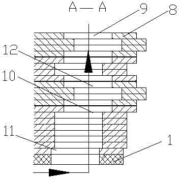
[0032] see figure 1 , a generator rotor ventilation slot structure, including slot bottom pads 1, rotor windings 2, under-wedge pads 3, damping windings 4 and rotor slot wedges 5, the rotor winding 2 consists of multiple copper bars 6 and inter-turn insulation 7 The copper bar 6 is formed by a plurality of copper wires 8 arranged side by side. The slot bottom pad 1, the rotor winding 2, the under-wedge pad 3, the damper winding 4 and the rotor slot wedge 5 are all provided with ventilation holes 9. In the axial direction of the rotor winding 2, there is a passage 10 which forms a radial ventilation with the ventilation hole 9, and any two adjacent copper bars 6 form the passage 10 in the axial direction of the rotor winding 2, and the entrance of the lower part of the passage 10 The tuyeres 11 are arranged obliquely along the direction of the cooling air, and the upper part of the channel 10 is provided with an air channel 12 with an "S" shape in cross section, and a plurality...
Embodiment 2
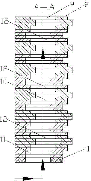
[0035] see figure 2, a generator rotor ventilation slot structure, including slot bottom pads 1, rotor windings 2, under-wedge pads 3, damping windings 4 and rotor slot wedges 5, the rotor winding 2 consists of multiple copper bars 6 and inter-turn insulation 7 The copper bar 6 is formed by a plurality of copper wires 8 arranged side by side. The slot bottom pad 1, the rotor winding 2, the under-wedge pad 3, the damper winding 4 and the rotor slot wedge 5 are all provided with ventilation holes 9. In the axial direction of the rotor winding 2, there is a passage 10 which forms a radial ventilation with the ventilation hole 9, and any two adjacent copper bars 6 form the passage 10 in the axial direction of the rotor winding 2, and the entrance of the lower part of the passage 10 The tuyeres 11 are arranged obliquely along the direction of the cooling air, and the upper part of the channel 10 is provided with an air channel 12 with an "S" shape in cross section, and a plurality...
Embodiment 3
[0039] see image 3 , a generator rotor ventilation slot structure, including slot bottom pads 1, rotor windings 2, under-wedge pads 3, damping windings 4 and rotor slot wedges 5, the rotor winding 2 consists of multiple copper bars 6 and inter-turn insulation 7 The copper bar 6 is formed by a plurality of copper wires 8 arranged side by side. The slot bottom pad 1, the rotor winding 2, the under-wedge pad 3, the damping winding 4 and the rotor slot wedge 5 are all provided with ventilation holes 9. In the axial direction of the rotor winding 2, there is a passage 10 which forms a radial ventilation with the ventilation hole 9, and any two adjacent copper bars 6 form the passage 10 in the axial direction of the rotor winding 2, and the entrance of the lower part of the passage 10 The tuyeres 11 are arranged obliquely along the direction of the cooling wind, and the upper part of the channel 10 is provided with three "S"-shaped air channels 12 in cross section, and the three "S...
PUM
 Abstract
Description
Claims
Application Information
 - R&D
- Intellectual Property
- Life Sciences
- Materials
- Tech Scout
- Unparalleled Data Quality
- Higher Quality Content
- 60% Fewer Hallucinations
Browse by: Latest US Patents, China's latest patents, Technical Efficacy Thesaurus, Application Domain, Technology Topic, Popular Technical Reports.
© 2025 PatSnap. All rights reserved.Legal|Privacy policy|Modern Slavery Act Transparency Statement|Sitemap|About US| Contact US: help@patsnap.com


