
Capacitance midpoint potential balancing device on SVG (Static VAR Generator) direct current side and control method of capacitance midpoint potential balancing device

A DC side capacitance and potential balance technology, which is applied in the direction of circuit devices, AC network circuits, output power conversion devices, etc., can solve problems such as the midpoint potential imbalance of DC side capacitors, and achieve simple control and simple control principles Effect

Active Publication Date: 2015-03-11
SHANDONG ELECTRIC POWER ENG CONSULTING INST CORP
View PDF4 Cites 9 Cited by
  • Summary
  • Abstract
  • Description
  • Claims
  • Application Information

AI Technical Summary

Problems solved by technology

[0005] The purpose of the present invention is to solve the above-mentioned technical problems, and provide a device for balancing the midpoint potential of the capacitor on the DC side of the SVG and its control method. Reactive power compensation provides better technical guarantee

Method used


Image

  • Capacitance midpoint potential balancing device on SVG (Static VAR Generator) direct current side and control method of capacitance midpoint potential balancing device
  • Capacitance midpoint potential balancing device on SVG (Static VAR Generator) direct current side and control method of capacitance midpoint potential balancing device
  • Capacitance midpoint potential balancing device on SVG (Static VAR Generator) direct current side and control method of capacitance midpoint potential balancing device

Examples


Embodiment Construction

[0041] The specific implementation manners of the present invention will be further described in detail below in conjunction with the accompanying drawings and embodiments.

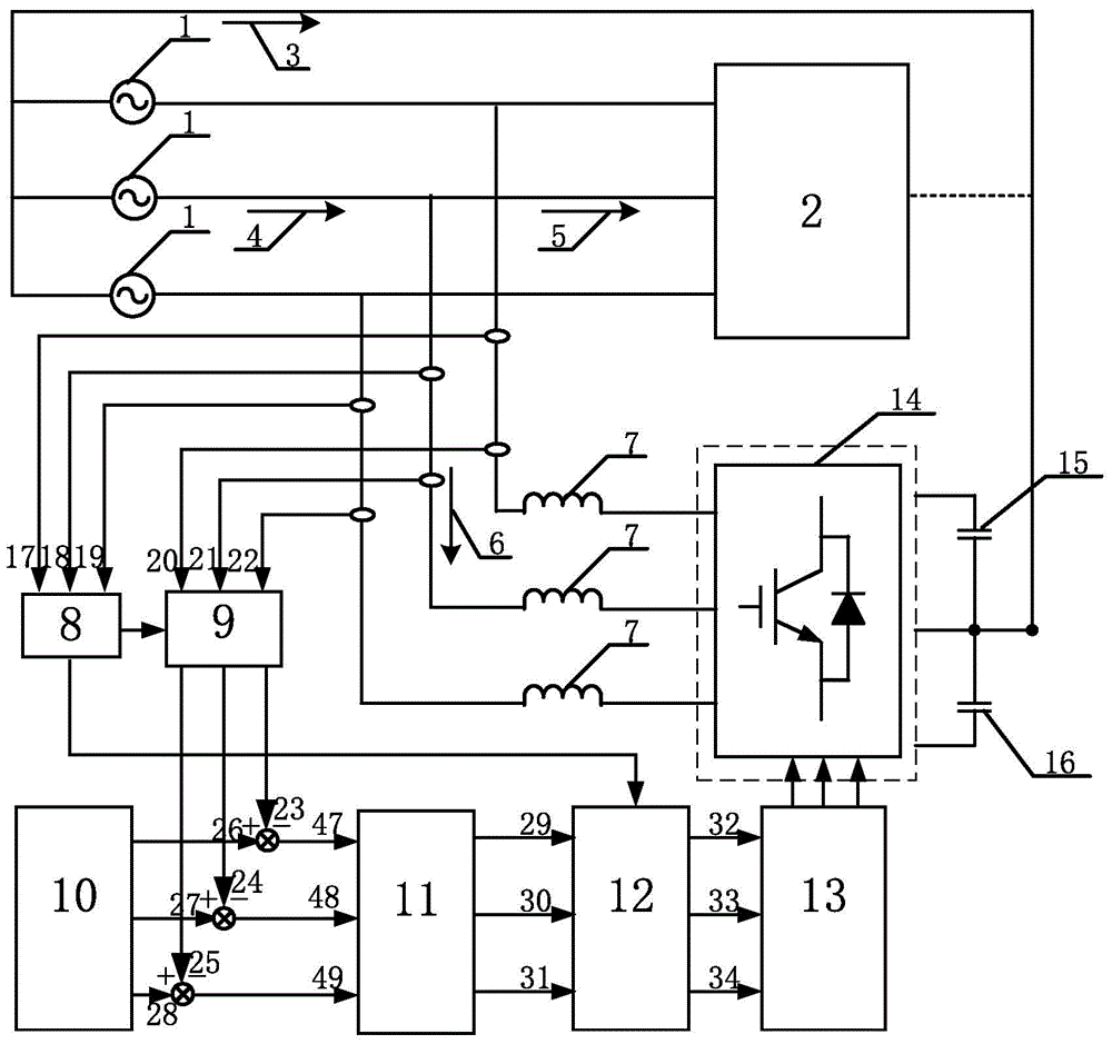
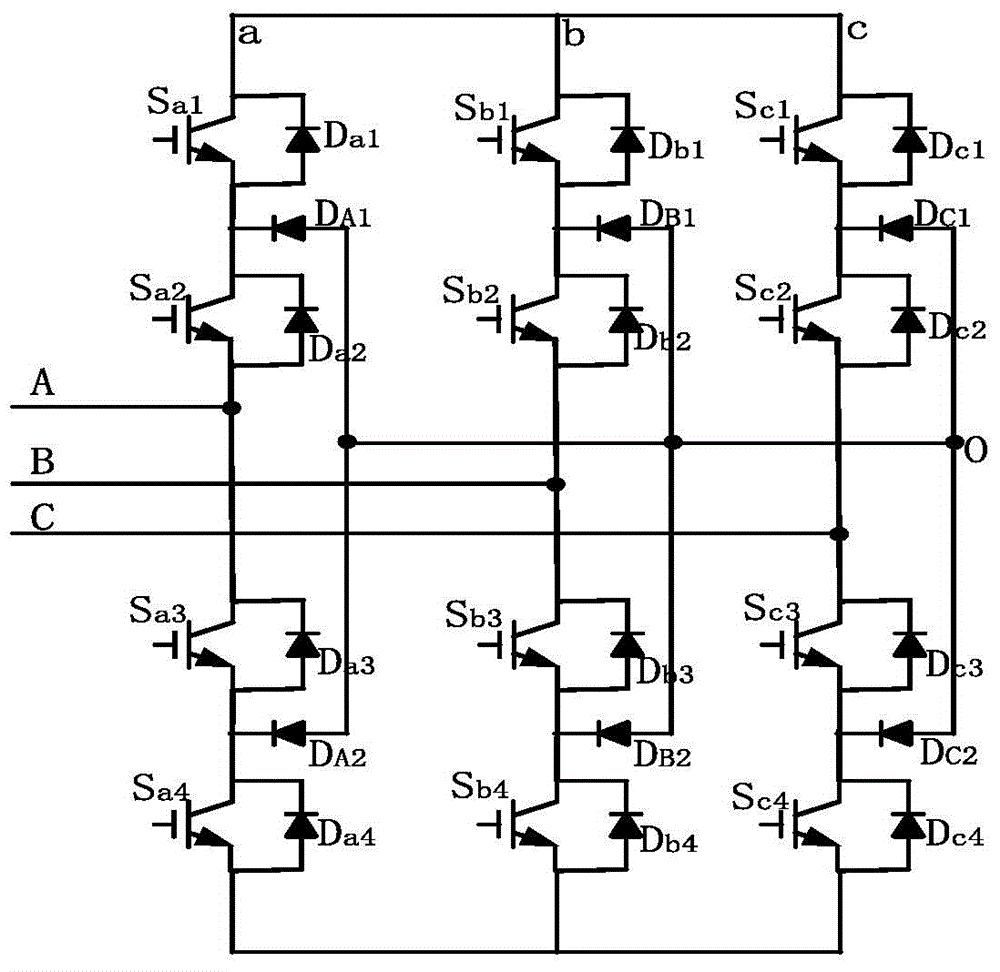
[0042] like figure 1 As shown, this embodiment provides a diode-clamped three-level static var generator DC side capacitor midpoint potential balance device, including static var generator (SVG) main circuit, measurement control system, diode clamp A bit-type three-level voltage source converter (VSC) circuit 14 and a parallel capacitor on the DC side. SVG main circuit is suitable for low-voltage power supply network.

[0043] The static var generator (SVG) main circuit includes a three-phase power supply 1, a three-phase load 2, and an AC reactor 7; the three-phase power supply 1 is a symmetrical three-phase power supply, and the three-phase load 2 is a three-phase unbalanced load.

[0044] One branch of the three-phase power supply 1 is connected in series with the three-phase load 2; the other branch...


PUM


Abstract

The invention discloses a capacitance midpoint potential balancing device on an SVG (Static VAR Generator) direct current side and a control method of the capacitance midpoint potential balancing device. The control method comprises the following steps: a branch of a three-phase source supply is connected with a three-phase load; the other branch of the three-phase source supply is in series connection with an alternating current reactor, a diode clamping type multi-level inverter voltage source converter (VSC) and a direct current side parallel capacitor sequentially; a measurement control system is in parallel connection between the three-phase supply source and the alternating current reactor; each phase bridge arm in the diode clamping type multi-level inverter voltage source converter is both connected with two series-connected clamping diodes. The capacitance midpoint potential balancing device and the control method disclosed by the invention has the benefits that the control principle is simple, and the control method is simple and convenient to implement; the capacitance midpoint potential balancing device is mainly used for study on the unbalanced capacitance midpoint potential on the direct current side of the diode clamping type three-potential static VAR generator; the control effect is independent from a modulation ratio and power factors of the system, so that theoretically the fluctuation of the midpoint can be controlled within a small range.

Description

technical field [0001] The present invention relates to the electrical industry, in particular to a diode-clamped three-level static var generator (SVG) DC side capacitor midpoint potential balance device and its control for reactive power compensation research on power networks method. Background technique [0002] In recent years, with the rapid development of the economy, the loads in the power grid, including reactive loads, have continued to increase substantially, and the grid connection of distributed new energy sources such as solar energy and wind energy has also greatly increased the complexity of the power grid, especially various power electronic devices. After the introduction of the power grid, the structure of the power grid has undergone major changes, and more and more reactive loads such as nonlinear loads and impact loads have brought great challenges to power quality. Therefore, the research on reactive power compensation devices has important very impor...

Claims


Application Information

Patent Timeline
Patent Type & Authority Applications(China)
IPC IPC(8): H02J3/18H02M7/487
CPCY02E40/30H02J3/1807H02M7/487
Inventor 毛戈王磊孙立军史朝晖孙永刚张洪霞
Owner SHANDONG ELECTRIC POWER ENG CONSULTING INST CORP
Learn More