Far-end time synchronization igniting control circuit used for launch control equipment and control method thereof
An ignition control and circuit technology, which is applied in the remote timing ignition control circuit and its control field, can solve problems such as different ignition delays of power devices, failure to meet the test purpose, and impact on launch tasks, so as to reduce complex execution actions, The effect of avoiding delay and saving development resources
- Summary
- Abstract
- Description
- Claims
- Application Information
AI Technical Summary
Problems solved by technology
Method used
Image
Examples
Embodiment 1
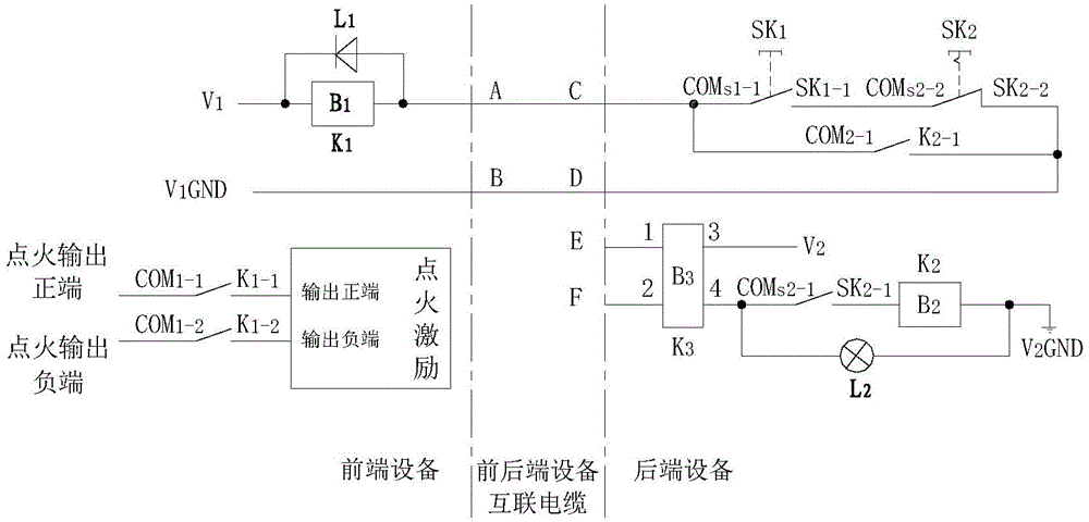
[0029] The present invention provides a remote timing ignition control circuit for the transmission and control equipment, the circuit controls the output of the ignition excitation; the power supply signal of the circuit includes two circuits: a positive voltage signal V 1 and a negative voltage signal V 1 GND, positive voltage signal V 2 and a negative voltage signal V 2 GND.
[0030] The circuit is divided into a front-end equipment circuit and a back-end equipment circuit, wherein the front-end equipment circuit is integrated in the front-end equipment of the transmission and control equipment, and the back-end equipment circuit is integrated in the back-end equipment of the transmission and control equipment.
[0031] Front-end equipment circuit:
[0032] The front-end equipment circuit includes an electromagnetic relay K 1 and freewheeling diode L 1 .
[0033] Electromagnetic relay K 1 with wire package B 1 and contacts, select the electromagnetic relay K 1 The ...
Embodiment 2
[0050] According to the circuit provided in Embodiment 1, this embodiment provides a remote timing ignition control method for the transmission and control equipment, and the method includes the following steps:
[0051] S1, keep the instantaneous self-locking button switch SK 1 In the initial state unchanged, press the instantaneous self-locking button switch SK 2 . When the system signal is introduced to the back-end equipment through the external contact points E and F and lasts for a set time, the solid state relay K 3 When the input terminal of the previous stage is connected, the output terminal of the subsequent stage is turned on, and the normally closed contact SK is at this time 2-2 Open, normally open contact SK 2-1 closed, by a positive voltage signal V 2 Via solid state relay K 3 , normally open contact SK 2-1 , and package B 2 to the negative voltage signal V 2 GND forms the first power supply path, and the normally open contact K 2-1 closed, by a positi...
PUM
 Abstract
Description
Claims
Application Information
 - R&D
- Intellectual Property
- Life Sciences
- Materials
- Tech Scout
- Unparalleled Data Quality
- Higher Quality Content
- 60% Fewer Hallucinations
Browse by: Latest US Patents, China's latest patents, Technical Efficacy Thesaurus, Application Domain, Technology Topic, Popular Technical Reports.
© 2025 PatSnap. All rights reserved.Legal|Privacy policy|Modern Slavery Act Transparency Statement|Sitemap|About US| Contact US: help@patsnap.com

