Material clamp and multifunctional manipulator shift conveyer of cup-making stack equipment
A transmission device and clamping clamp technology, which is applied in the field of multifunctional manipulator shifting transmission device, can solve the problems of crooked and scattered distribution, upside down, inconvenient automatic transmission, etc., and achieve wide application range, high production efficiency, and material transmission effect Good results
- Summary
- Abstract
- Description
- Claims
- Application Information
AI Technical Summary
Problems solved by technology
Method used
Image
Examples
Embodiment 1
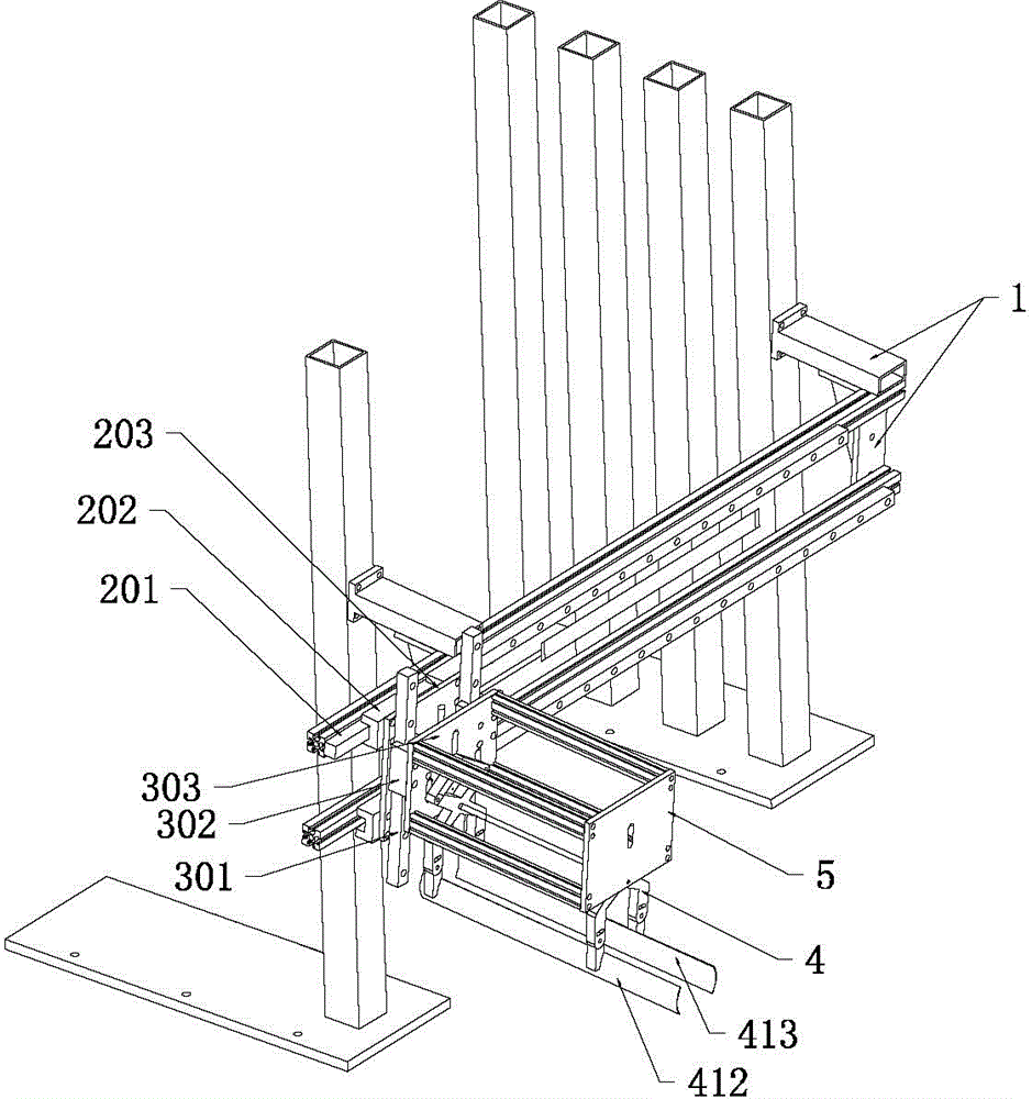
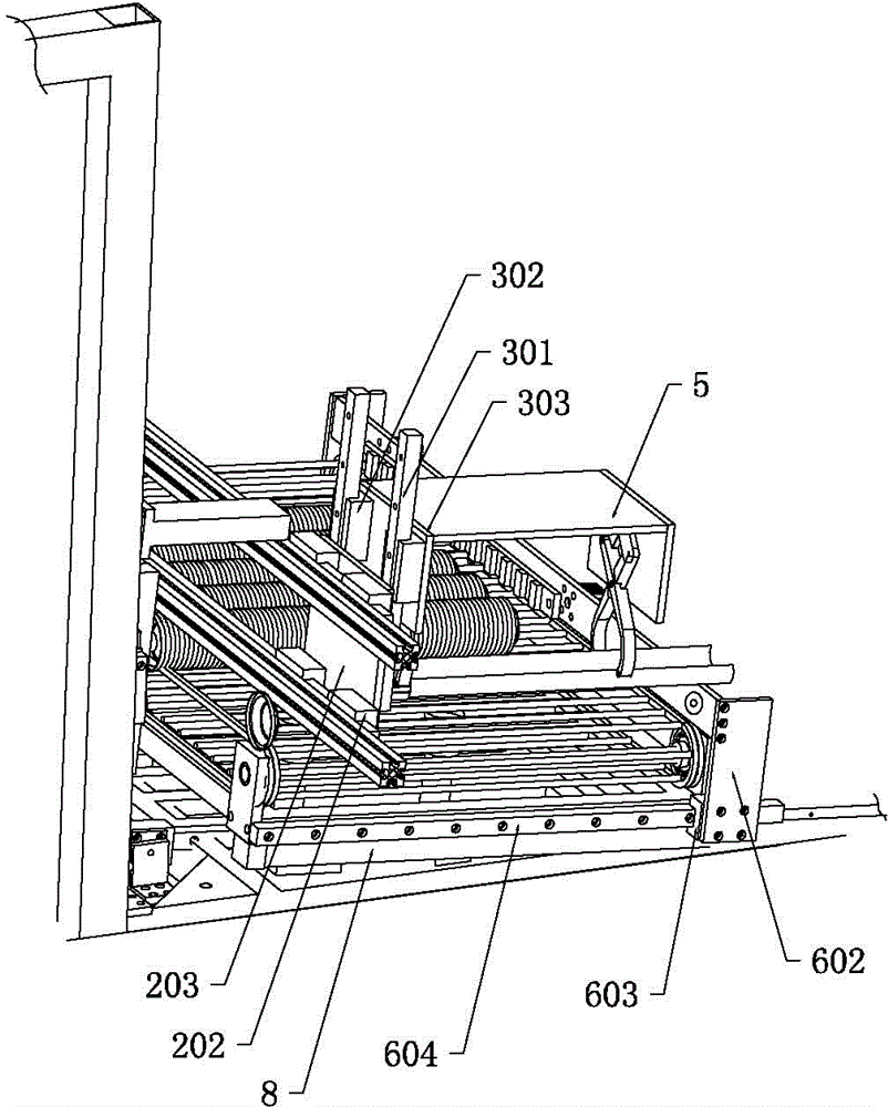
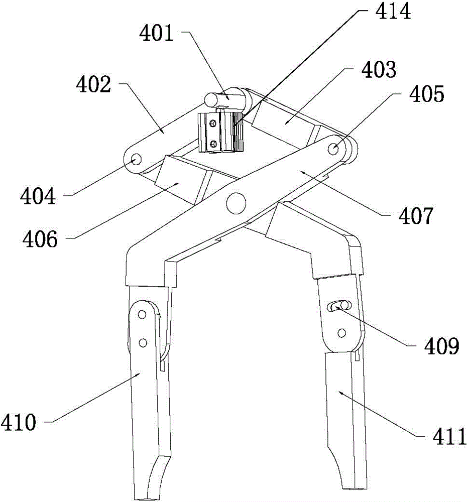
[0050] Such as figure 1 and figure 2 As shown, a multi-functional manipulator shifting transmission device of a cup making and stacking equipment in this embodiment includes a controller (not shown in the figure), a clamping tongs support frame 5, a clamping tongs 4, and a controller The clamping tongs clutch cylinder 414 , the translation drive unit and the lifting drive unit are electrically connected respectively, and the clamping tongs 4 are fixed on the clamping tongs support frame 5 .
[0051] The translation driving unit includes a translation sliding rail 201, a translation sliding slider 202, a translation support plate 203 and a translation driving device (not shown in the figure), and the translation driving device is electrically connected to the controller. It should be noted that this embodiment The translational driving device can be an air cylinder, which is named as a translational driving air cylinder in this embodiment, but it should be noted that the presen...
Embodiment 2
[0062] The main technical solution of this embodiment is basically the same as that of Embodiment 1, and the features not explained in this embodiment are explained in Embodiment 1, and will not be repeated here. This embodiment is different on the basis of embodiment 1 in that, as Figure 6 As shown, the guide member of the guide assembly in this embodiment is a push sliding rod 608, the sliding member is a free sliding sleeve, and also includes a pushing sliding sleeve 607, and the cover abutting unit also includes an abutting plate pushing member 606, which The pusher 606 of the abutment plate is arranged in an "L", the piston rod of the push cylinder 605 is fixedly connected with the middle part of the pusher 606 of the abutment plate, and one end of the pusher 606 of the abutment plate is fixed on the push sliding sleeve 607, and the push sliding sleeve 607 Set on push slide bar 608. The pushing cylinder 605 drives the pushing part 606 of the abutting plate to move, and ...
Embodiment 3
[0064] The main technical solutions of this embodiment are basically the same as those of Embodiment 1, and the features not explained in this embodiment are explained in Embodiment 1, and will not be repeated here. The difference of this embodiment is that the guide assembly includes a sliding rod, a free sliding sleeve and a pushing sliding sleeve, and the abutment plate 601 is fixedly connected to the free sliding sleeve, which can be welded, integrally formed, or bolted.
PUM
 Abstract
Description
Claims
Application Information
 - R&D Engineer
- R&D Manager
- IP Professional
- Industry Leading Data Capabilities
- Powerful AI technology
- Patent DNA Extraction
Browse by: Latest US Patents, China's latest patents, Technical Efficacy Thesaurus, Application Domain, Technology Topic, Popular Technical Reports.
© 2024 PatSnap. All rights reserved.Legal|Privacy policy|Modern Slavery Act Transparency Statement|Sitemap|About US| Contact US: help@patsnap.com


