
Machine tool propulsion mechanism

A technology of propulsion mechanism and propulsion motor, which is applied in metal processing machinery parts, metal processing equipment, feeding devices, etc., can solve the problems of unstable propulsion speed, inaccurate final position of workpiece, and difficult processing.

Inactive Publication Date: 2015-03-11
CHANGZHOU HOUXIAO YUHENG CURTAIN WALL
View PDF0 Cites 0 Cited by
  • Summary
  • Abstract
  • Description
  • Claims
  • Application Information

AI Technical Summary

Problems solved by technology

[0002] In the process of machine tool processing, the methods of propulsion include manual propulsion, conveyor belt propulsion, hydraulic cylinder propulsion, etc. Such traditional propulsion methods sometimes have unstable propulsion speeds, resulting in collisions between the workpiece and the machine tool, making the final result of the workpiece The position is not accurate and difficult to process

Method used


Image

  • Machine tool propulsion mechanism

Examples


Embodiment Construction

[0009] The present invention will be further described in detail below in conjunction with the accompanying drawings and specific embodiments.

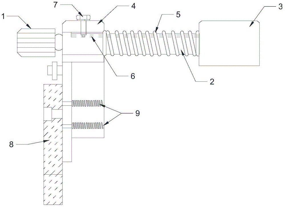
[0010] Such as figure 1 As shown, the propulsion mechanism of the machine tool includes a propulsion motor 1, the output end of the propulsion motor 1 is connected to the propulsion rod 2, and the other end of the propulsion rod 2 is connected to the propulsion block 3, and the connection between the propulsion rod 2 and the propulsion motor 1 is provided with The fixed plate 4, at the position of the fixed plate 4 to the push block 3, the outer ring of the push rod 2 is covered with a spring 5, and the push rod 2 is also provided with a groove 6, and the fixed plate 4 is provided with a groove 6 The position corresponds to the screw 7, and the screw 7 is stuck in the groove 6.

[0011] The fixed plate 4 is fixed to the machine tool 8 by nuts, and also includes a spring group 9 parallel to the push rod 2, and the spring 9 group is lo...


PUM


Abstract

The invention discloses a machine tool propulsion mechanism, which comprises a propulsion motor, wherein the outer end of the propulsion motor is connected with a propulsion rod; the other end of the propulsion rod is connected with a propulsion block; the junction of the propulsion rod and the propulsion motor is provided with a fixing plate; a spring sheathes the outer ring of the propulsion rod at the position from the fixing plate to the propulsion block. A groove is formed in the propulsion rod, the fixing plate is provided with a screw corresponding to the groove in the position, and the screw is clamped in the groove. The invention provides the machine tool propulsion mechanism to realize the propulsion of a workpiece in a machine tool processing process, and the machine tool propulsion mechanism has the advantages of stable propulsion process, no violent collision and quickly-adjustable propulsion speed.

Description

technical field [0001] The invention relates to the field of machine tool workpiece accessories, in particular pointing out a machine tool propulsion mechanism. Background technique [0002] In the process of machine tool processing, the methods of propulsion include manual propulsion, conveyor belt propulsion, hydraulic cylinder propulsion, etc. Such traditional propulsion methods sometimes have unstable propulsion speeds, resulting in collisions between the workpiece and the machine tool, making the final result of the workpiece The location is inaccurate and difficult to process. Contents of the invention [0003] The object of the present invention is to propose a machine tool propulsion mechanism to realize the propulsion of the workpiece during the machining process of the machine tool, and the propulsion process is stable without violent collision, and the propulsion speed can be adjusted quickly. [0004] The technical scheme that realizes the object of the presen...

Claims


Application Information

Patent Timeline
Patent Type & Authority Applications(China)
IPC IPC(8): B23Q5/28
CPCB23Q5/28B23Q2705/14
Inventor 孔立峰
Owner CHANGZHOU HOUXIAO YUHENG CURTAIN WALL
Learn More