
High-precision hot melt glue nozzle and hot melt glue gun

A hot-melt glue gun, high-precision technology, applied in coatings, devices for coating liquid on the surface, etc., can solve problems such as inaccurate angles, easy to break or drill deviation, etc., to improve cleaning efficiency and accurate disassembly , high precision effect

Inactive Publication Date: 2015-03-11
QUANZHOU NDC SPRAY COATING SYST FABTING
View PDF14 Cites 1 Cited by
  • Summary
  • Abstract
  • Description
  • Claims
  • Application Information

AI Technical Summary

Problems solved by technology

[0002] As known, a gas channel and a glue channel are formed in the hot melt glue nozzle. During operation, the glue channel outputs the glue line, and the gas channel outputs the air flow, and the trajectory of the glue line is changed by the air flow, such as the spiral arrangement in the glue channel The gas channel on the outer periphery can output spiral air flow to make the glue liquid line output in a spiral shape, and the inclined gas channel arranged symmetrically on both sides of the glue liquid channel can output cross air flow to make the glue liquid line output in a wave shape. Therefore, The arrangement and inclination angle of the gas channel require high-precision processing. The traditional process is to use drilling equipment to process the gas channel on the nozzle, and adjust the feed angle of the drill bit to process the gas channel with different inclination angles and arrangements. This processing method There are many uncertain factors, which can easily cause inaccurate angles. For example, the drill bit is in the middle of the drilling hole, because it is relatively thin, it is easy to break or drill off.

Method used


Image

  • High-precision hot melt glue nozzle and hot melt glue gun
  • High-precision hot melt glue nozzle and hot melt glue gun
  • High-precision hot melt glue nozzle and hot melt glue gun

Examples


Embodiment 1

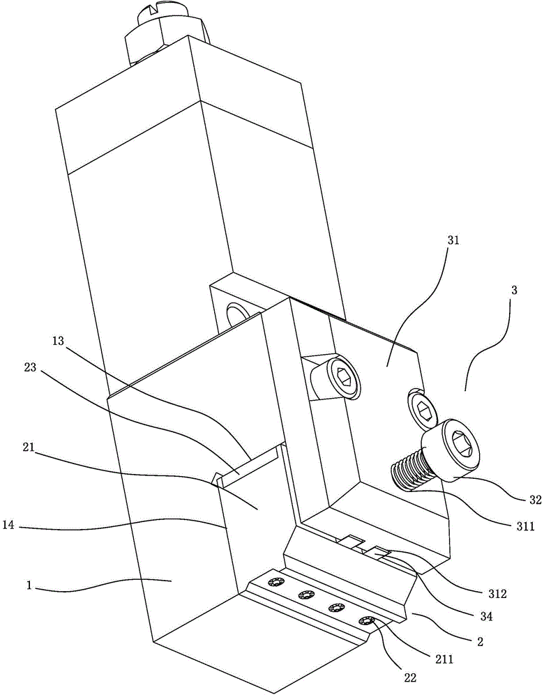
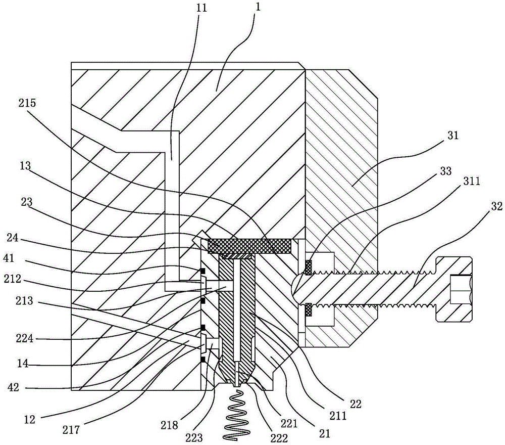
[0050] Embodiment one, with reference to Figure 5 to Figure 9 As shown, a high-precision hot melt glue gun includes a glue gun body 1 and a hot melt glue nozzle 2 installed at the lower end of the glue gun body 1 through a locking mechanism 3,

[0051] The inside of the glue gun body 1 is formed with a liquid supply channel 11 and an air supply channel 12. The glue gun body 1 is provided with a pneumatic control valve (not shown) for on / off the liquid supply channel 11. The side of the lower end of the glue gun body 1 An installation groove for installing the hot melt adhesive nozzle 2 is formed, and the installation groove has a horizontal base surface 13 and a vertical base surface 14 .

[0052] The hot melt adhesive nozzle 2 includes a nozzle body 21 and several cores 22. The nozzle body 21 is a metal block with a flat top surface 216 and a back surface 214. The top surface 216 of the nozzle body 21 is attached to the horizontal base surface 13 of the installation groove. ...


PUM

PropertyMeasurementUnit
Helix angleaaaaaaaaaa

Abstract

The invention discloses a high-precision hot melt glue nozzle. The high-precision hot melt glue nozzle is mounted on a glue gun body; the glue gun body is provided with a solution supply channel and a gas supply channel; the high-precision hot melt glue nozzle comprises a nozzle body and a core body, wherein a containing hole penetrating the upper and lower parts of the nozzle body is formed inside the nozzle body; the core body is matched with the containing hole and is closely embedded in the containing hole; a glue solution channel with an opening in the lower end surface of the core body is formed inside the core body; at least two gas channels extending to the lower end surface of the core body are formed in the peripheral surface of the core body; a gas channel is formed between the gas channel and the wall of the containing hole. The glue solution channel and the solution supply channel are communicated for outputting an glue solution line during operation, the gas channel and the gas supply channel are communicated for outputting gas flow, the glue solution line is output in a specific shape under the action of the gas flow, and the machining of the gas channel can adopt a mode of milling a groove in the conical peripheral surface of the core body to replace the traditional drilling mode, so that the formation mode of the gas channel is more accurate and efficient than the traditional drilling technology.

Description

technical field [0001] The invention relates to a hot melt glue nozzle and a hot melt glue gun. Background technique [0002] As known, a gas channel and a glue channel are formed in the hot melt glue nozzle. During operation, the glue channel outputs the glue line, and the gas channel outputs the air flow, and the trajectory of the glue line is changed by the air flow, such as the spiral arrangement in the glue channel The gas channel on the outer periphery can output spiral air flow to make the glue liquid line output in a spiral shape, and the inclined gas channel arranged symmetrically on both sides of the glue liquid channel can output cross air flow to make the glue liquid line output in a wave shape. Therefore, The arrangement and inclination angle of the gas channel require high-precision processing. The traditional process is to use drilling equipment to process the gas channel on the nozzle, and adjust the feed angle of the drill bit to process the gas channel with...

Claims


Application Information

Patent Timeline
IPC IPC(8): B05C5/04B05C11/10
CPCB05C11/10B05C5/001
Inventor 黄向明
Owner QUANZHOU NDC SPRAY COATING SYST FABTING
Learn More