Ultrasonic gauge

An ultrasonic and measuring instrument technology, applied in the field of ultrasonic measuring instruments, can solve problems such as incomplete removal, reduced measurement accuracy, and scrapped pipelines, so as to increase product interchangeability, reduce mold costs, and reduce defective products. Effect

Inactive Publication Date: 2015-03-04
HUIZHI INSTR
View PDF9 Cites 1 Cited by
  • Summary
  • Abstract
  • Description
  • Claims
  • Application Information

AI Technical Summary

Problems solved by technology

Although the cost of all low-melting material pipelines is lower than that of high-melting material pipelines, the joints of low-melting materials are relatively easy to be damaged when fastened, and slipping is prone to occur after repeated assembly
[0003] The existing low-melting material pipelines attach ultrasonic transducers to the outer surface of the pipeline, which will reduce the measurement accuracy because it is difficult to control the verticality of the transducer when it is attached to the outer surface of the pipeline, resulting in Deviation occurs when the transducer is facing each other
Moreover, the transducer cannot be completely removed after it is attached. If there is a problem with the transducer, it cannot be reprocessed, and it needs to be scrapped together with the pipe and the transducer.
[0004] Existing pipes need to be made with moulds. The type of teeth on the connector (American system, British system), the length of the pipe and teeth need to be determined before the mold is made, and the type and size of the connector should be changed after the mold is completed. It will be more difficult, and many times it is necessary to open a new mold to make the pipeline
[0005] The existing low-melting material pipeline is composed of multiple accessories, which are generally formed by ultrasonic welding. Because the ultrasonic welding process is relatively unstable and the adjustment requirements are relatively complicated, the defective product rate is relatively high and expensive equipment is required. The connection part of the low-melting material pipeline is relatively low in pressure resistance, causing the connection position to be easily broken
[0006] The existing U-shaped pipeline ultrasonic transducers are placed above the inlet and outlet of the pipeline, so that it is difficult for the air to flow out of the pipeline, resulting in a decrease in measurement accuracy

Method used


Image

  • Ultrasonic gauge
  • Ultrasonic gauge
  • Ultrasonic gauge

Examples


Embodiment Construction

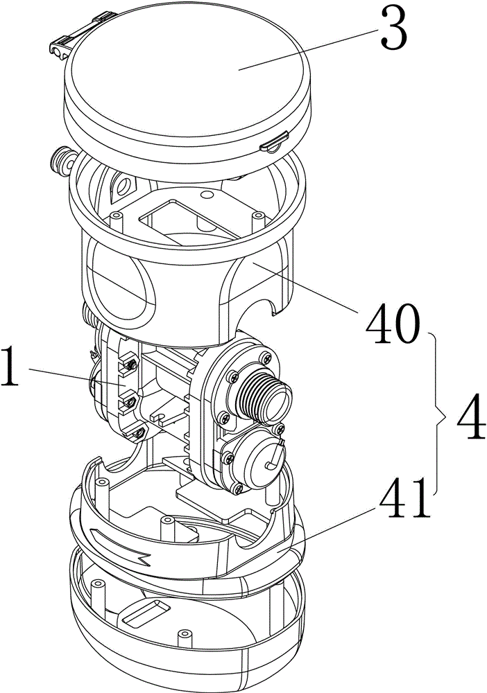
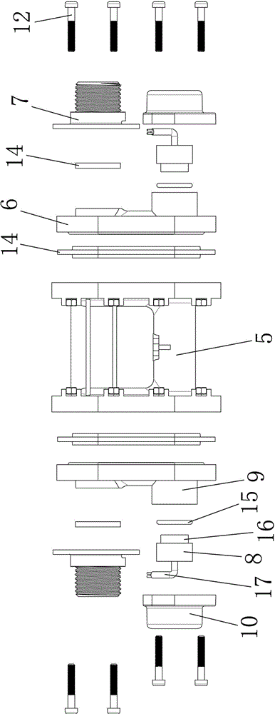
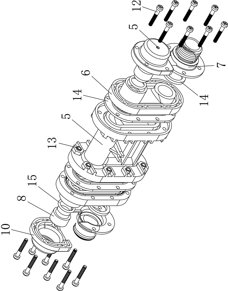
[0030] The present invention will be described in further detail below in conjunction with the accompanying drawings.

[0031] like figure 1 , 2 , 3, 4, and 5, an ultrasonic meter includes a U-shaped pipe 1 with two ends, an electronic circuit 2, a first housing 3 for accommodating the electronic circuit 2, and accommodating the U-shaped pipe 1 of the second housing 4 and more than two ultrasonic transducers 8, the ultrasonic transducers 8 are connected to the electronic circuit 2 through corresponding wires 17; wherein, the ultrasonic transducers 8 are waterproof , and pass through the inner wall of the U-shaped pipe 1 in the second housing 4 , and directly contact the liquid in the U-shaped pipe 1 . The ultrasonic transducer 8 is directly attached to the inner wall of the U-shaped pipe 1 and is in direct contact with the fluid, and the surrounding edge of the transducer is closely attached to the surrounding edge of the pipe to ensure that the two transducers can be instal...


PUM


Abstract

The invention discloses an ultrasonic gauge which comprises a U-shaped pipeline with two ends, an electronic circuit, a first shell, a second shell and more than two ultrasonic transducers. The first shell is used for accommodating the electronic circuit, the second shell is used for accommodating the U-shaped pipeline, and the ultrasonic transducers are connected to the electronic circuit by corresponding wires; the waterproof ultrasonic transducers are penetratingly arranged on the inner wall of the U-shaped pipeline in the second shell and are in direct contact with liquid in the U-shaped pipeline. The ultrasonic gauge has the advantages that the ultrasonic transducers can be in direct contact with the metered liquid and can be assuredly perpendicularly mounted, and information can be accurately received by the transducers in an opposite transmission manner.

Description

technical field [0001] The invention relates to the technical field of metering fluid flow equipment, in particular to an ultrasonic meter. Background technique [0002] Traditional ultrasonic gauges use pipes with high-melting materials (such as metals), and pipes that replace high-melting materials with low-melting materials (such as plastics and other thermoplastic materials) appeared later. Although the cost of all low-melting material pipelines is lower than that of high-melting material pipelines, the joints of low-melting materials are relatively easy to be damaged during fastening, and slipping is prone to occur after repeated assembly. [0003] The existing low-melting material pipelines attach ultrasonic transducers to the outer surface of the pipeline, which will reduce the measurement accuracy because it is difficult to control the verticality of the transducer when it is attached to the outer surface of the pipeline, resulting in Deviation occurs when the trans...

Claims


Application Information

Patent Timeline
Patent Type & Authority Applications(China)
IPC IPC(8): G01F1/66
Inventor 苏尚轺
Owner HUIZHI INSTR
Why Eureka
Try Eureka