A continuous stamping die for manufacturing antenna terminals of wearable belt devices

An antenna terminal, stamping die technology, applied in the direction of manufacturing tools, metal processing equipment, forming tools, etc., can solve the problems of high production cost, reduced enterprise efficiency, waste of human resources, etc., to reduce usage, improve production efficiency, reduce The effect of maintenance costs

Inactive Publication Date: 2016-06-15
四川瑞宝电子股份有限公司
View PDF5 Cites 0 Cited by
  • Summary
  • Abstract
  • Description
  • Claims
  • Application Information

AI Technical Summary

Problems solved by technology

In this multiple stamping process, multiple single-process molds are required to complete, which wastes a lot of human resources of the production enterprise, the process is cumbersome, and the cost of mold manufacturing and maintenance is increased at the same time, and rapid mass production cannot be achieved.
It leads to high overall production cost of the enterprise, prolongs the production cycle of the product, and reduces the efficiency of the enterprise

Method used


Image

  • A continuous stamping die for manufacturing antenna terminals of wearable belt devices
  • A continuous stamping die for manufacturing antenna terminals of wearable belt devices

Examples


Embodiment Construction

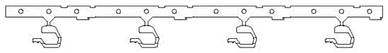
[0021] Design a continuous progressive mold that includes all processing steps for the manufacture of antenna terminals for wearable belt devices, and a set of molds can achieve high-precision terminal production.

[0022] The main template of the mold includes an upper mold and a lower mold. The upper mold includes: upper mold base 1, upper backing plate 2, upper splint 3, stop plate 4, stripping plate 5, and the lower mold includes: lower template 8, lower backing plate 9 , Lower mold base 10. Assembly method: the upper backing plate 2 is fixed on the upper die base 1, the upper splint 3 is locked on the upper die base 1 with the long bolts passing through the upper backing plate 2, the upper splint 3 and the die base 1 are positioned with long pins, The baffle plate 4 is fixed on the stripper plate 5, the lower backing plate 9 is fixed on the lower mold base 10, the lower template 8 is locked on the lower mold base 10 with the long bolts passing through the lower backing pl...


PUM


Abstract

The invention discloses a continuous stamping die for manufacturing an antenna terminal of wearable equipment. The continuous stamping die has the improvement points that all steps of the continuous stamping die which is used for producing the antenna terminal of the wearable equipment are focused on a die, an upper clamping plate is provided with male dies of all the steps, a stripper plate is provided with insert cores of the male dies of all the steps, and a lower die plate is provided with female dies of all the steps. According to the continuous stamping die disclosed by the invention, through the action of the male dies and the female dies, continuous production is realized, the production efficiency is increased, the using amount of the dies is reduced, and the manufacturing cost of an enterprise is reduced.

Description

technical field [0001] The invention relates to a continuous stamping die, in particular to a continuous stamping die for manufacturing antenna terminals of belt threading equipment. Background technique [0002] At present, in the prior art, the manufacture of antenna terminals for wearable belt devices requires multiple steps to complete, such as blanking, 90° bending, 59° bending, 5° bending, 9° bending and other steps. In this multiple stamping process, multiple single-process molds are required to complete, which wastes a lot of human resources of the production enterprise, the process is cumbersome, and at the same time increases the cost of mold manufacturing and maintenance, and cannot achieve rapid mass production. It leads to high overall production cost of the enterprise, prolongs the production cycle of products, and reduces the efficiency of the enterprise. Contents of the invention [0003] In order to overcome the defect that the existing manufacturing of t...

Claims


Application Information

Patent Timeline
Patent Type & Authority Patents(China)
IPC IPC(8): B21D37/12B21D43/00B21D45/08
CPCB21D37/12B21D43/003B21D45/08
Inventor 陈光君
Owner 四川瑞宝电子股份有限公司
Why Eureka
Try Eureka