
Massage shower head

A technology of shower and massager, which is applied to vibration massage, massage auxiliary products, jet devices, etc., can solve the problems of unpractical massage function, unstable, stuck, etc., to achieve better massage effect, stable massage intensity, and easy disassembly easy-to-install effect

Active Publication Date: 2015-03-04
XIAMEN DELMEI SANITARY WARE
View PDF7 Cites 3 Cited by
  • Summary
  • Abstract
  • Description
  • Claims
  • Application Information

AI Technical Summary

Problems solved by technology

Most of the showers with massage function in the prior art use water flow to impact the impeller so that the impeller drives the massage disc to move directly or through the cam to realize the massage function. However, the use of water flow as the power has the following disadvantages: The power that can be provided is limited, which leads to limitations in the massage intensity of the massage disc; the power that the water flow can provide is small and unstable, resulting in weak massage intensity of the massage disc. High friction, easy to jam, and even make it unusable
Thereby the massage function of this massage shower head of prior art is not practical in real life

Method used


Image

  • Massage shower head
  • Massage shower head
  • Massage shower head

Examples


Embodiment 1

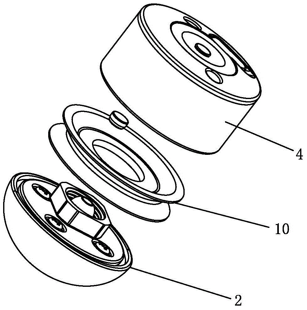
[0037] See Figure 1-Figure 8 As shown, a massage shower of the present invention, the massage shower is specifically a hand shower, which includes a shower body 1, and also includes a vibration massager attached to the shower body 1, and the vibration massager includes a massage head 2 and a vibration motor 3, the vibration motor 3 is built in the massage head 2, and the power supply is used as the electric driving force; the massage head 2 is movable relative to the shower body 1, so as to realize the vibration massage driven by the vibration motor 3.

[0038] As a preference, the shaft center of the massage head 2 is provided with a ball head shaft 23; the vibration massager also includes an installation body 4 attached to the shower body 1, and the installation body 4 is provided with The shaft hole, the ball head of the ball joint shaft 23 is movably socketed in the shaft hole. Here, the vibrating massager may not be provided with the installation body 4 , but directly c...

Embodiment 2

[0048] See Figure 9-Figure 12 As shown, the massage shower of the present invention differs from the first embodiment in that the massage head 2 is located at the back of the water outlet of the shower body 1 . Similar to Embodiment 1, the shower body 1 is composed of a main body rear cover 11, a water diversion body 12, a surface cover 13, a rubber water outlet body 14, a main body front cover 15, a connecting seat 17, a mandrel 18, a suspension water outlet mechanism 16, etc. , the difference from the first embodiment is: the middle part of the main body rear cover 11 is provided with a circular passage through which the front and back sides communicate with each other. After the main body 1 is assembled, the circular channel, the water diversion body 12, the surface cover 13, the circular hole on the rubber water outlet body 14, and the main body back cover 11 are correspondingly matched to form the installation groove 111, and the installation groove 111 The notch is loc...


PUM


Abstract

The invention discloses a massage shower head, which comprises a shower head body, and a vibration massager connected to the shower head body, wherein the vibration massager comprises a massage head and a vibration motor; the vibration motor is built in the massage head and adopts a power supply as electrical driving force; the shower head is movably arranged relative to the shower head body, and vibration massage is realized under the drive of the vibration motor. According to the massage shower head, the power of the vibration massager is sufficient and stable, the massage strength of the massage head can achieve the optimal state and is stable, the phenomenon of jamming cannot occur when the massage head makes contact with parts of a human body during the actual application process, relevant parts of the human body can be continuously massaged in a vibration way, and the massage effect is truly achieved for users.

Description

technical field [0001] The invention relates to a shower head, in particular to a shower head with a massage function. Background technique [0002] Showers, including hand showers, head showers, etc., are a type of bathing equipment commonly used in bathrooms. The traditional shower only has the function of water outlet, which has a single function, and it is difficult to meet the needs of people in today's society. For this reason, many shower heads with massage function have appeared in the prior art, which not only enriches the functions of the shower head, but also enables users to enjoy the massage effect during bathing. Most of the showers with massage function in the prior art use water flow to impact the impeller, so that the impeller drives the massage disc to move directly or through the cam to realize the massage function. However, the use of water flow as the power has the following disadvantages: The power that can be provided is limited, which leads to limit...

Claims


Application Information

Patent Timeline
Patent Type & Authority Applications(China)
IPC IPC(8): B05B1/18B05B15/00A61H23/02
CPCA61H23/02B05B1/18B05B15/00
Inventor 严永强潘国能陈付燻
Owner XIAMEN DELMEI SANITARY WARE
Learn More