Laminated poultry raising equipment
A layered and described layered technology, applied in the poultry industry, poultry cages or houses, applications, etc., can solve the problems of reducing processing difficulty and processing cost, and easy damage of deep groove ball bearings, so as to reduce processing costs and reduce Processing difficulty, the effect of increasing aesthetics and practicality
- Summary
- Abstract
- Description
- Claims
- Application Information
AI Technical Summary
Problems solved by technology
Method used
Image
Examples
Embodiment 1
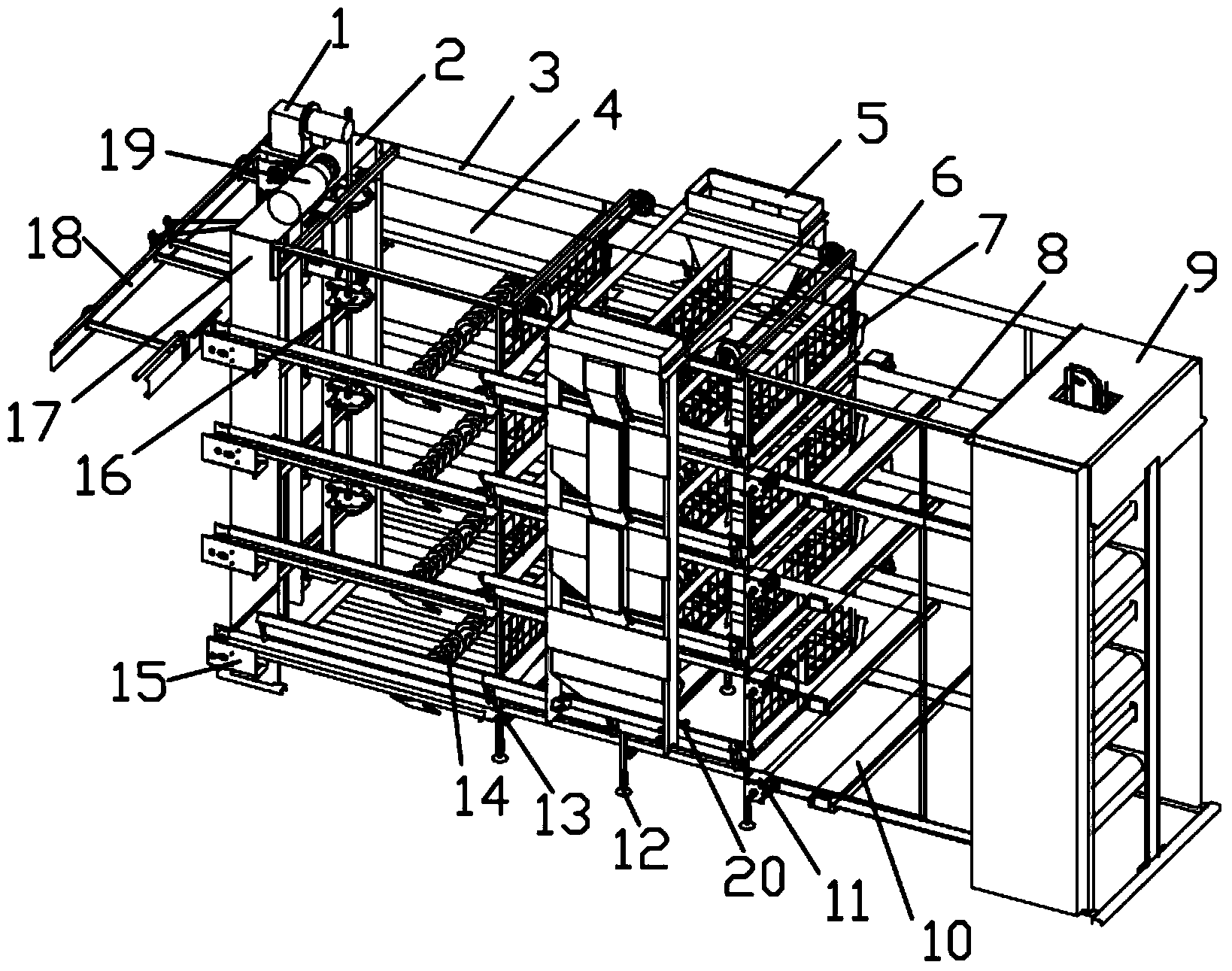
[0040] like figure 1 As shown, a kind of stacked poultry raising equipment provided by the present invention, the equipment includes a frame structure 2, the outside of the frame is provided with a head frame side plate 17, and the middle part of the frame 2 is stacked with several mesh structures The poultry cage 6 of each layer of poultry cage 6 is provided with a food trough bracket 13 fixedly connected to both sides of the frame 2 at the outer and lower position of the cage wall of each layer of poultry cage 6, and the food trough bracket 13 is fixedly equipped with an opening Upward U-shaped food trough 4, the outside of food trough 4 is provided with food trough baffle 7, and the top of described frame 2 is provided with the walking guide rail 3 that is arranged symmetrically, and described walking guide rail 3 is equipped with the top that reciprocates in horizontal direction. Feeder 5, the opening of the lower hopper provided on each floor of the feeder 5 corresponds t...
Embodiment 2
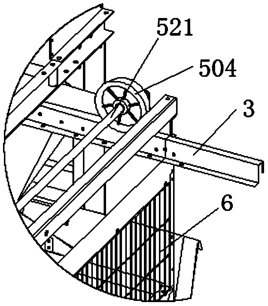
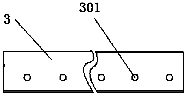
[0042] like Figure 2-7 As shown, the present invention provides a walking guide rail 3 of a feeder for stacked poultry farming equipment. The walking guide rail 3 includes short boards 302 and long boards 304 bent perpendicularly to the top board 303 respectively. The long boards 304 are provided with The bottom plate 305 parallel to the top plate 303 and bent in the opposite direction, the cross section of the walking guide rail 3 is a U-shaped structure with an opening downward, and the U-shaped structure includes short plates 302 perpendicular to the sides of the top plate 303 The side and the side of the long plate 303, the side of the long plate 304 is provided with a bottom plate 305 parallel to the side of the top plate 303 and bent in the opposite direction, the long plate 304 is provided with a first installation hole 301, The bottom plate 305 defines a second mounting hole 306 . like figure 2 As shown, pass through the second mounting hole 306 with bolts to be fi...
Embodiment 3
[0044] like Figure 8-11As shown, the difference between the walking guide rail 3 of a stacked poultry feeding equipment feeding machine provided in this embodiment and the embodiment 2 is that several pull plates 308 are provided between the bottom plate 305 and the long plate 304 The short plate 302 is connected with the L-shaped plate to form a U-shaped first roller groove 309 with an upward cross-section. The side of the outer wheel of the walking wheel 504 can be snapped into the first roller groove 309, which can achieve the effect of force balance during use, and the support and reinforcement of the pull plate 308 and the support plate 307 ensure the firmness of its structure And it is not easy to deform, and at the same time, it solves the problem that the roller often falls off the long pipe.
PUM
 Abstract
Description
Claims
Application Information
 - R&D Engineer
- R&D Manager
- IP Professional
- Industry Leading Data Capabilities
- Powerful AI technology
- Patent DNA Extraction
Browse by: Latest US Patents, China's latest patents, Technical Efficacy Thesaurus, Application Domain, Technology Topic, Popular Technical Reports.
© 2024 PatSnap. All rights reserved.Legal|Privacy policy|Modern Slavery Act Transparency Statement|Sitemap|About US| Contact US: help@patsnap.com


